Robotics: How to Get Started — Part 6: Logical and Bit-Wise Operators
By John Blankenship View In Digital Edition
Extracting information from many robotic sensors requires both logical and bit-wise operations. Understanding how and when to use various operations can make programming your robot easier, more efficient, and less prone to errors.
Many hobbyists (especially those new to robotics) seem to have trouble utilizing logical and bit-wise operators. In some cases, the problem is that they don’t fully understand the details of how the operators work, but even beginners that have a reasonable understanding of the operations often use them improperly, or at least inefficiently.
The Operations
The two operations that we’ll discuss here are AND and OR (both logical and bit-wise). Logical operations basically involve TRUE or FALSE assertions. Figure 1 shows examples of logical AND and OR operations and how they control a program’s flow.
IF Expr1 AND Expr2
// these statements will
// execute only if BOTH
// Expr1 and Expr2 are TRUE
ENDIF
IF Expr1 OR Expr2
// these statements will
// execute if EITHER Expr1
// or Expr2 (or both) is TRUE
ENDIF
Figure 1.
Expressions
An expression can be nearly any mathematical or logical statement. Figure 2 shows some examples.
3<5 Always TRUE
(6-2)>8 Always FALSE
X<Y TRUE if the value of X is less than the value of Y
(X+Y)>=2 TRUE if the value of X+Y is greater than or equal to 2
Y == 8 TRUE if the value of Y is equal to 8
Y=8 Same as above in RobotBASIC which allows both versions
12 Any non-zero value is TRUE (even -2, 1.8, .03, for example)
0 Any zero value will be FALSE
X TRUE if the value of X has any non-zero value
Figure 2.
Study the figure to see that any expression will be true if the current values for the expression create a non-zero value.
This works with logical expressions because truthful logic statements always evaluate to a value of 0 for FALSE or 1 for TRUE. This also means that any non-zero numeric expression will be considered TRUE.
Alternative Syntax
In the above examples, we used the operators AND and OR which are often used in languages like BASIC that strive for readability. More cryptic languages (like C, for example) use && for AND and || for OR.
RobotBASIC was designed to be a powerful yet easy language to learn, but also one that can help you transition to other languages. For that reason, you can use both styles of syntax and mix them freely throughout a program.
Using the Simulator
In order to make the concepts in this article easier to understand, let’s use RobotBASIC’s integrated robot simulator to create some meaningful examples. Figure 3 shows a depiction of the simulated robot.
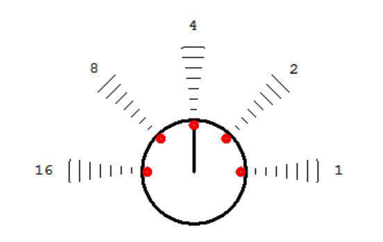
Figure 3.
It’s just a circle with a single line indicating the current heading. The robot has many sensors. There are five perimeter sensors around the front of the robot, indicated in the figure by the small circles.
Imagine that each of these sensors contains an infrared emitting diode (LED) that can send out a burst of light as indicated in the figure. These beams of light are low intensity so their usability dissipates quickly, perhaps extending out five or six inches on a real robot. If one of the beams strikes a nearby object, some of the light can be reflected back toward the robot. Each of the perimeter sensors also contain an IR detector that can sense this reflected light as an indicator of some external obstacle.
The sensed data from the sensors is stored as a five-bit binary number, with each bit representing one of the sensors (bit values of 0 means nothing is seen and 1 indicates some reflected light has been detected). Notice the numbers at the end of each light beam in Figure 3. They represent the value of each bit’s position in the data.
RobotBASIC’s rFeel() function is used to obtain the sensor data. If the value of the data is 4, for example, it means the middle sensor has detected an object. A value of 16, as another example, would indicate an object left of the robot. If two or more sensors detect objects, the data value would be the sum of the values for the individual sensors.
A Meaningful Example
Let’s assume our robot is moving towards a wall and we want it to use its sensors to avoid a collision by turning away from the wall. Figure 4 shows examples of the sensor data as the robot approaches the wall from various angles.
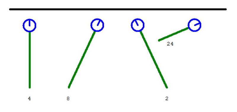
Figure 4.
Starting from the left side of Figure 4, we see that if the robot is approaching at a 90° angle only the middle sensor detects the wall, giving a value of 4 (the robot is stopping as soon as the wall is detected). If the robot approaches at a slight angle, the data could be 8 or 2 (Figure 3). The last example in Figure 4 has the robot approaching the wall at an angle that causes two of the sensors (8 and 16) to detect the wall at the same time, which means the data will be the sum of the detections (in this case, 24).
Analyzing the Data
If we look at what numbers the sensors are returning, we can get a reasonable idea of where the wall is in relationship to the robot. Let’s look at a few examples to demonstrate some points. The program fragment in Figure 5 tries to make the robot turn around (something close to 180°) when it detects a wall that is more or less in front of the robot (rather than on one side or the other).
while TRUE // loop forever
d = rFeel()
if d=2 OR d=4 OR d=8
rTurn 160+random(40)
elseif d=16
rTurn 30
elseif d=1
rTurn -30
else
rForward 1
endif
wend
Figure 5.
If the wall is detected beside the robot, then the robot will turn so that it moves away from the wall using a small angle that is somewhat similar to the approach angle.
Notice that the first IF statement uses logical operations to check if any of the middle three sensors detect a wall. If TRUE, then the robot turns a random amount (180 ± a random left or right offset of up to 20°). There are actually some problems with this statement, but we’ll return to that shortly.
The remainder of the code fragment checks for side sensor detections and turns the robot away from the wall at a reasonable angle. If none of these conditions are detected, the robot just moves forward slightly. As stated earlier, there are problems, and if we execute the code, Figure 6 shows a possible outcome.
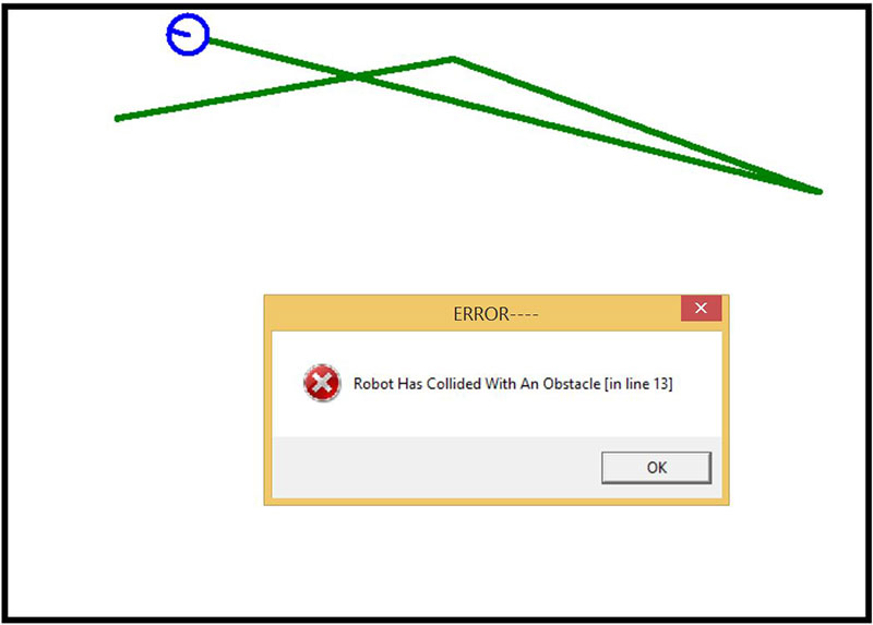
Figure 6.
Everything starts off great (see Figure 6). As the robot approaches the first wall, the active left sensor turns the robot to the right. When it sees the next wall with one of the three middle sensors, it turns around and heads back to the left.
When it encountered the top wall again though, the wall was not detected and a collision occurred (causing an error and stopping the program). Can you speculate why this error occurred? Try to come up with something before proceeding.
Revealing the Error
The problem with the collision in this example is that the robot approached the wall in a manner that triggered both the 1 and 2 sensors, giving the sensor data a value of 3 — which the program did not check for.
This means the robot just continues forward, and since the two right-side sensors both remain active, the wall is never detected. It’s possible that right before the collision, the middle sensor may also be triggered giving a total sum of 1+2+4.
Since neither 3 nor 7 is checked for or handled, a collision will eventually occur. It might take a while, but since there are random numbers controlling the turns, eventually a sensor situation will arise that was not considered.
Fixing the Problem
We could use logical operations to check for all the possible considerations. For example, instead of the line elseif d=1, we could use elseif d=1 OR d=3 OR d=7, which allows us to consider all the possible options we identified earlier.
Now that we understand the problem, it should be obvious that the same thing occurs with potential collisions on the left side of the robot. It’s not as obvious, but even the initial check for a wall ahead of the robot has potential problems. The program only checks to see if the sensor data was 2, 4, or 8.
Depending on the angle of approach, the value could have been 2+4 or 8+4, so we need to check 6 and 12 too. If the wall has some curves and contours, then you might even have to check for 14 (2+4+8) and 10 (2+8).
Obviously, the statements checking for all possible options are getting complicated. Luckily, there’s an easier way to approach this problem and it involves bit-wise operations.
Bit-Wise AND and OR
Just as X>3 && Y is a logical AND operation, and A=2 || B<0 is a logical OR operation, you can use a single & and | to indicate bit-wise AND and OR situations. RobotBASIC also allows you to use bAND and bOR if you prefer to have more readable code. Remember a logical AND means that both expressions have to be TRUE. The same concept applies to bit-wise AND, but not to two expressions; instead, to two bits.
Let’s assume we have two numbers; for example, 12 and 5. Twelve is 01100 in binary and five is 00101. If we form a bit-wise AND of these two numbers, the result is calculated by doing an AND on the two least-significant bits, then the next two bits, etc., until the most-significant bit is done.
The answer from each of the bit actions becomes a bit in the final number produced by the operation. Bit-wise OR operations are just like the bAND except that the output bit will be a 1 if either (or both) of the two bits being considered are 1s, as shown in Figure 7.
| Decimal | Binary | |
| First number | 12 | 01100 |
| Second number | 5 | 00101 |
| 12&5 | 4 | 00100 |
| 12|5 | 13 | 01101 |
Figure 7.
Using Bit-Wise Operators
Remember how complicated it was to use logical operators to detect if one or more of the three middle sensors on the robot detected a wall (if d=2 OR d=4 OR d=8 OR d=6 OR d=10 OR d=12)? We can perform the same functionality with bitwise operations using if d&14 (because 14 is binary 01110).
It works because the expression d&14 will have at least one 1 in it as long as one or more of the three middle robot sensors is triggered (and any 1 will make the number a non-zero or TRUE).
This means we can easily modify the earlier program to make it work the way we expected. I’ll leave that as a simple exercise for the reader.
For now, though, let’s use our new skills to make the program much better. Figure 8 contains a program fragment that attempts to do this.
while TRUE // loop forever
d=rFeel()
if d // see if we have reached a wall yet
rForward 3 // move slightly forward to get better readings
d=rFeel() // and take a new reading
else
rForward 1 // because no wall has been detected
endif
// d will be zero at this point if a wall is not detected
// but make an appropriate turn if d has a non-zero value
if d=4 // approaching wall perpendicularly
rTurn 170+random(20) // turn around almost completely
rForward 10 // move away from the wall
elseif d&16 // hitting wall on left at a shallow angle
rTurn 30+random(10) // turn a little right
rForward 10 // move away from the wall
elseif d&1 // hitting wall on right at a shallow angle
rTurn -(30+random(10)) // turn a little left
rForward 10 // move away from the wall
elseif d&2 // coming in at an intermediate angle, wall on right
rTurn -(70+random(30)) // large turn left
rForward 10 // move away from the wall
elseif d&8 // coming in at an intermediate angle, wall on left
rTurn 70+random(30) // large turn right
rForward 10 // move away from the wall
endif
wend
Figure 8.
Analyzing the New Program
The program in Figure 8 tries to make the robot always turn away from the wall using a reasonable angle. Think of it as a ball bouncing off a wall. The ball should angle away from wall with a similar angle that it approached it. This is not an easy task with only five sensors, but the program does a reasonable job as shown by Figure 9.
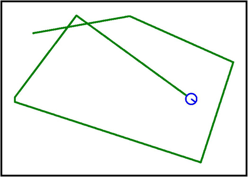
Figure 9.
If you wanted to build a real robot that would randomly roam your house, this is a decent algorithm because the robot seems to make reasonable turns related to how it approaches the wall.
We are about out of space, but let’s get a working overview of the program. It starts by checking if a wall has been detected. If no wall is detected, the robot just moves forward a tiny amount on its journey toward the next wall detection. If a wall is detected, the robot moves a little forward so that multiple sensors might be engaged because that can give us more accurate information about how much the robot needs to turn (when compared to the likelihood that only one sensor might be triggered).
After the move, the program gathers the new sensor data by taking another reading of the sensors. At this point in the program, the variable d will either be zero (and nothing will happen till the next time through the loop) or it will have some value, and some turn will be initiated. Let’s look at each of the possible options in the order they occur in the program.
If the front sensor is the only one on — meaning a fairly direct approach angle — the robot will turn away using something close to 180°. In this and all the other options, the robot moves forward slightly after the turn to ensure that no sensors are still touching the wall because if any sensor is still touching, it could trigger a new turn when the loop starts over. If the wall is detected on the robot’s left side, it turns slightly right. If detected on the right, it turns slightly left.
Notice that these actions are initiated anytime the left or right sensors are detected, regardless of any other sensors that might also be on. Finally, if none of the previous conditions were met, the program looks only at sensors 2 and 8 because they indicate a moderate angle approach and therefore produce a turn that will take the robot away from the wall at a similar angle.
More to Learn
There are many more topics associated with logical and bit-wise operations, but hopefully this short tutorial has gotten you off to a good start. Remember, you don’t have to always have a world-class problem to solve when you program.
Sometimes even a simple problem can force you to learn new concepts and develop new and interesting strategies. SV
Article Comments