
How to “Tram” Your CNC Router
By Roger Secura View In Digital Edition
After watching some of the YouTube videos on “tramming” a CNC router, it appeared to me there had to be a better way to align a motor or spindle. What I wanted was a tramming technique that didn’t involve the use of ‘playing cards’ and paper shims to level a 12” x 12” piece of glass. After burning up a few brain neurons, I came up with a system where I can manually “dial-in” a level surface with just four socket head screws — think leveling adjustment screws on the bottom four corners of your washer or dryer. Anyhow, in this article, we’ll take a look at what tramming a CNC router means, why you need to tram your machine, and the equipment and technique I use to tram mine.
TRAMMING – WHAT IS IT?
Tramming a CNC router is defined as squaring up the Z axis motor/spindle so that it’s perpendicular to a level router table in two directions: the X axis and Y axis. Look at Figure 1 and you’ll have a better understanding of this.
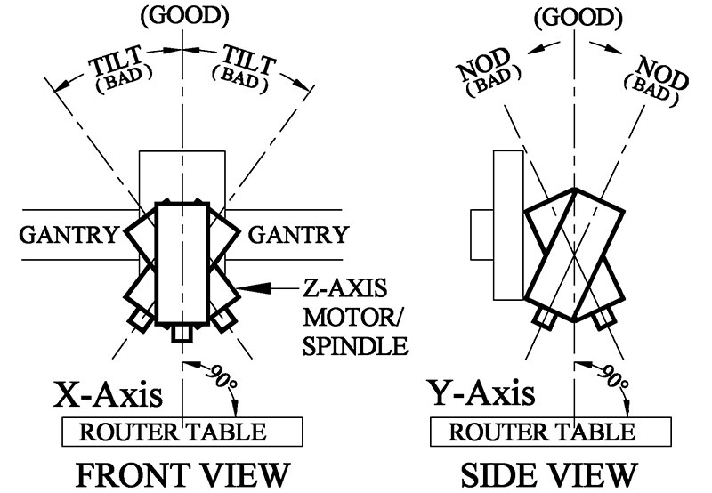
FIGURE 1.
Notice in the front view in Figure 1 how it’s possible for your CNC router motor or spindle to be tilting left or right of the vertical centerline. The tilt angles in the drawing were exaggerated for the sake of clarity.
Normally, we’re talking about thousandths to tens of thousandths of an inch of deflection from the vertical centerline.
The leaning left or right in the X axis direction is normally referred to as tilt; the leaning forward or backward in the Y axis direction is commonly referred to as nod — like when you nod your head back and forth when you’re really tired.
WHAT’S THE PROBLEM?
Whether you own a new or old CNC router, there’s a good possibility that your Z axis motor/spindle is out of vertical alignment.
Some of the detrimental effects of a misaligned motor are: a shorter tool bit life; chatter (vibration); and unsightly surface marks on your workpieces (wood).
GENERAL IDEA
An overview of the tramming process is in order here to give you a better idea of what we’re trying to achieve.
It’s unlikely that your router table top (a.k.a., spoiler board or waste board) is a perfectly level surface. So, we’re going to place a 12” x 12” mirror (a piece of glass works too) at the center of our router table. Using a “dial indicator,” the mirror will be leveled to a high degree of accuracy. This mirror will become our level reference plane to which we will adjust the tilt and nod of the Z axis motor/spindle.
Once the motor/spindle is adjusted correctly for nod and tilt, you can resurface your spoiler board and be assured it’s a perfectly level surface.
PIECES AND PARTS
You’ll need to make four corner brackets for the mirror as shown in Figure 2 and Figure 3.
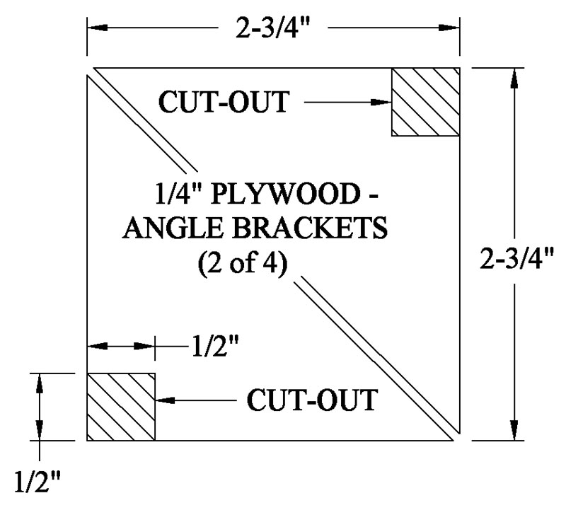
FIGURE 2.
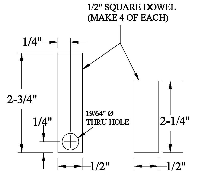
FIGURE 3.
Before you assemble the brackets, take the four socket head screws and sharpen (grind) the tips as shown in Figure 4. It should be mentioned here that the four screws are the key components in this design.
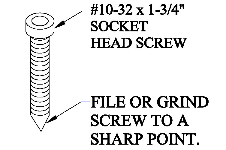
FIGURE 4.
The sharp ends of the screws will keep the mirror from moving around the router table during the leveling procedure.
Because they have 32 threads per inch, you can manually adjust the level of the mirror in minute increments (thousandths of an inch).
Now, assemble all the parts as shown in Figure 5. Watch out for those brass insert nuts. The slotted tops are easy to crack off with a screwdriver. I found that a wide chisel works best. Just apply a steady torque on the slotted head.
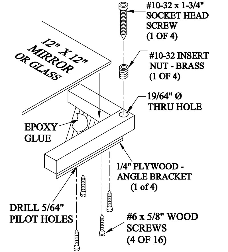
FIGURE 5.
At this point, you should put some target marks at the center and four corners of the mirror with a magic marker (see Figure 6). This will help you to repeatedly hit the same points on the mirror with the dial indicator.
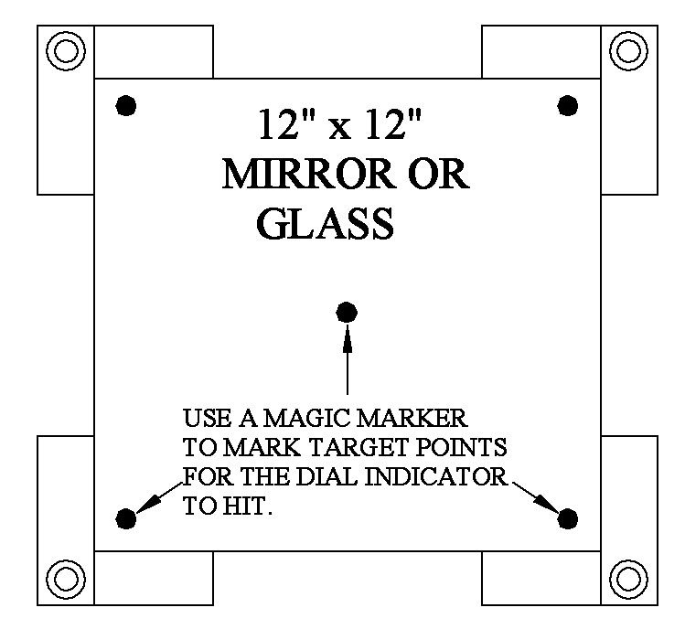
FIGURE 6.
TIME TO TRAM YOUR MACHINE
Place the mirror assembly in the center of your spoiler board as shown in Figure 7. Using just your thumb and finger (no tools), adjust the four corner screws so the mirror isn’t wobbling on the table.
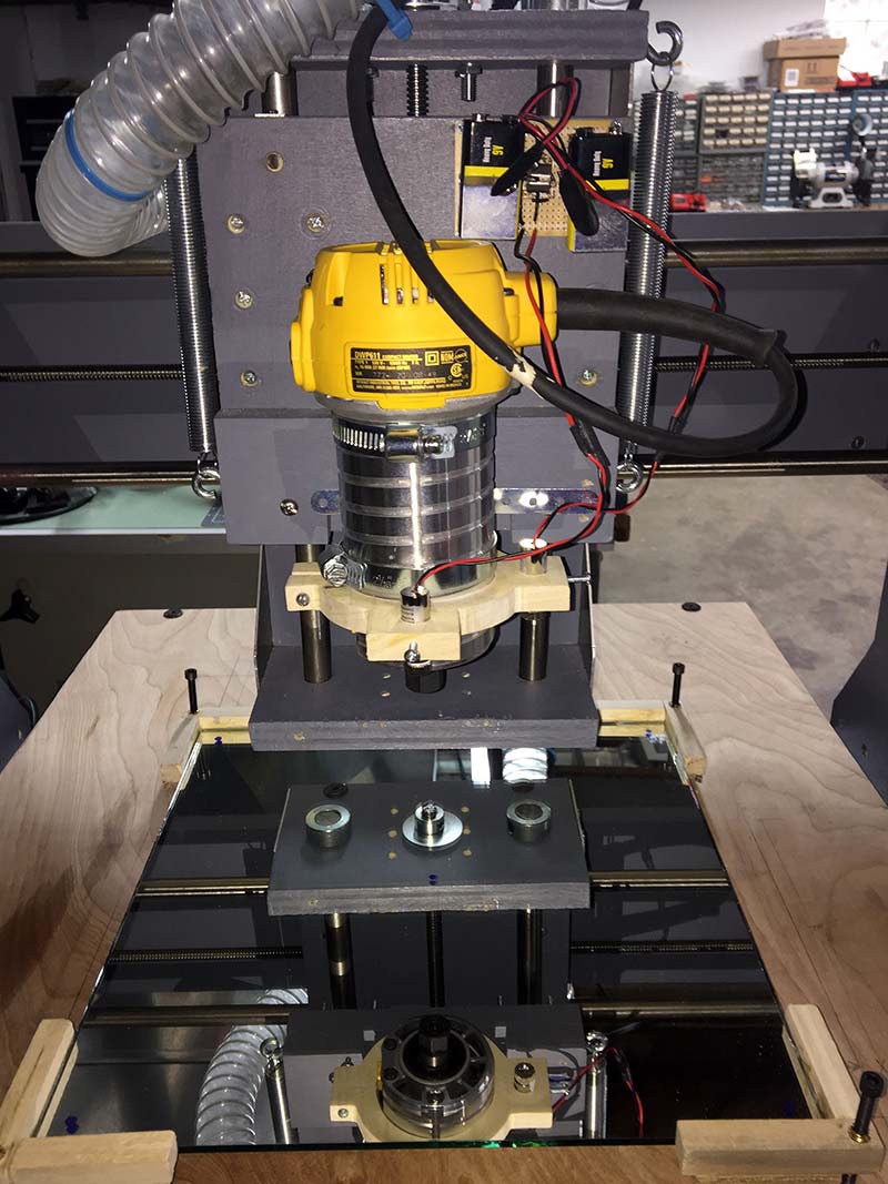
FIGURE 7.
Now — and this is important — use a rubber hammer and lightly tap on the top of each one of the four socket head screws. This will impale the sharp end of each screw into your spoiler board just enough to stop the mirror from moving around during the leveling process.
You’ll find the dial indicator has four tiny screws on the backside of the dial. Carefully remove them and rotate the back faceplate 90 degrees.
Now, insert the 1/4” x 2” bolt through the lug hole on the backside of the dial indicator; add a nut and tighten.
Finally, stick the 1/4” bolt into the router’s collet (chuck) and hand tighten as shown in Figure 8.
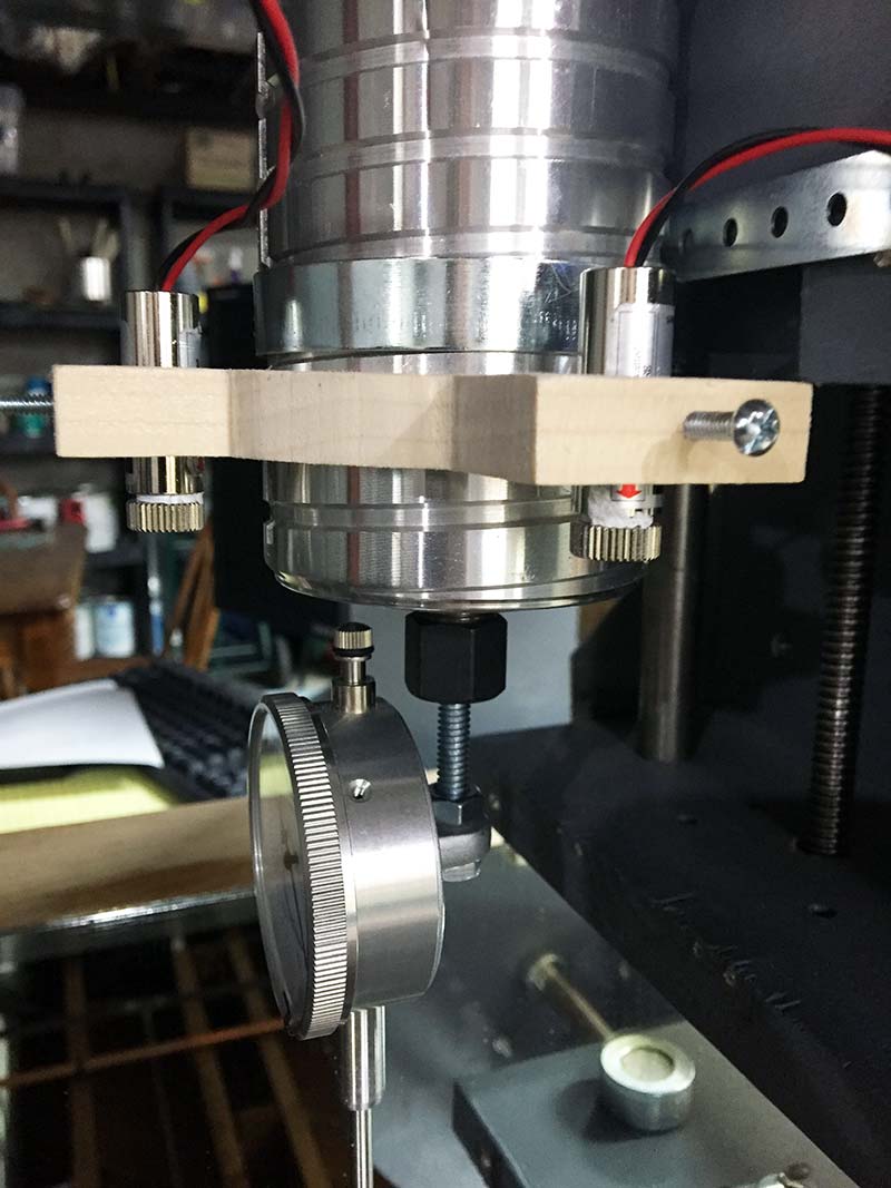
FIGURE 8.
Next, move the dial indicator to the center of the mirror. SLOWLY lower the dial’s plunger onto the mirror’s surface until the plunger is depressed about 1/4”. Now, rotate the outer rim of the dial indicator and set the pointer to the ‘zero’ mark.
Move the dial indicator to each one of the four corners of the mirror. Mark down the reading displayed on the dial for each corner. A high spot will move the dial in the positive direction (+10, +20, +30, etc. — clockwise).
A low spot will move the dial in the negative direction (-90, -80, -70, etc. — counterclockwise).
Next, move the dial indicator to the ‘highest’ corner of the four corners and rotate the rim of the dial indicator to set the pointer to the zero position.
ow, using the highest corner as a zero reference level, move the dial indicator to one of the other three lower corners. Slowly adjust the socket head screw and raise the corner until the dial indicator pointer returns to the zero mark.
Next, move the dial to the other two corners and adjust the socket head screws until they also read zero on the dial. Again, move the dial indicator around the four corners a few times to verify your readings. Adjust all four screws to return the dial pointer to zero.
The mirror is “perfectly” level when the dial indicator reads zero at all four corners.
The whole leveling procedure should take you less than 10 minutes.
ADJUSTMENT FOR NOD
In order to find the correct nod and tilt adjustments for your motor/spindle, you’ll need to make an aluminum extender arm fixture as shown in Figure 9.
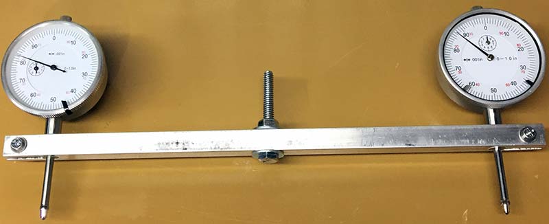
FIGURE 9.
Use the drawing in Figure 10 to make an extender arm fixture. You could make the arm out of wood, but unless you’re using a hard wood like oak, the arm will have too much flexibility to be useful.
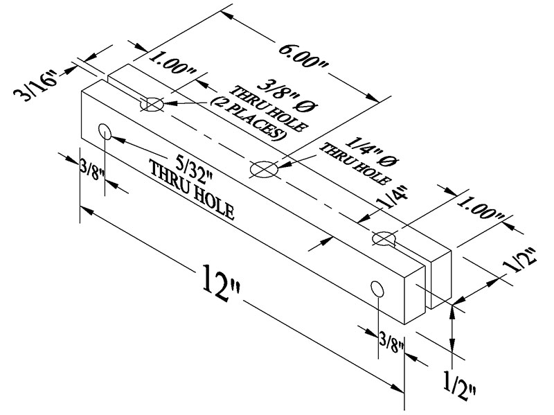
FIGURE 10.
Also, use a center punch and a drill press to mark and drill all the holes. No matter how good you are with tools, you won’t make straight (perpendicular) holes in the aluminum bar with a hand drill.
Now that you have a level mirror as a reference plane, insert the aluminum extender arm into the collet and hand tighten.
After the extender arm is secured, move the motor/spindle to the center of the mirror. (WARNING: Verify that you’ve unplugged the motor/spindle from its power source!)
As shown in Figure 11, swing the extender arm to the north/south position.
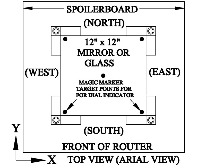
FIGURE 11.
Next, rotate the rim of each dial indicator until both pointers are sitting at the zero mark.
Now, SLOWLY lower the extender arm towards the mirror until one of the two plungers is depressed against the mirror about .080” (80 thousandths of an inch).
If the dial indicators don’t read the same number, slightly loosen the motor mounting bolts and adjust the motor/spindle until they match.
NOTE: Don’t use aluminum foil or paper to shimmy up the mounting plates in order to adjust for nod. Instead, buy yourself a set of steel “feeler” gauges ($5) that come in various standardized thicknesses–thousandths/inch.
Remember, as you adjust the motor for nod, the goal is not to try and return both dial pointers to the zero position, but to match the dial readings — regardless of what number they agree on.
The motor will be adjusted correctly for nod (i.e., perpendicular to the level mirror) when both dial indicators agree with each other at the north and south positions.
ADJUSTMENT FOR TILT
Once the motor/spindle is adjusted for nod, rotate the extension arm to the east/west positions as shown in Figure 12.
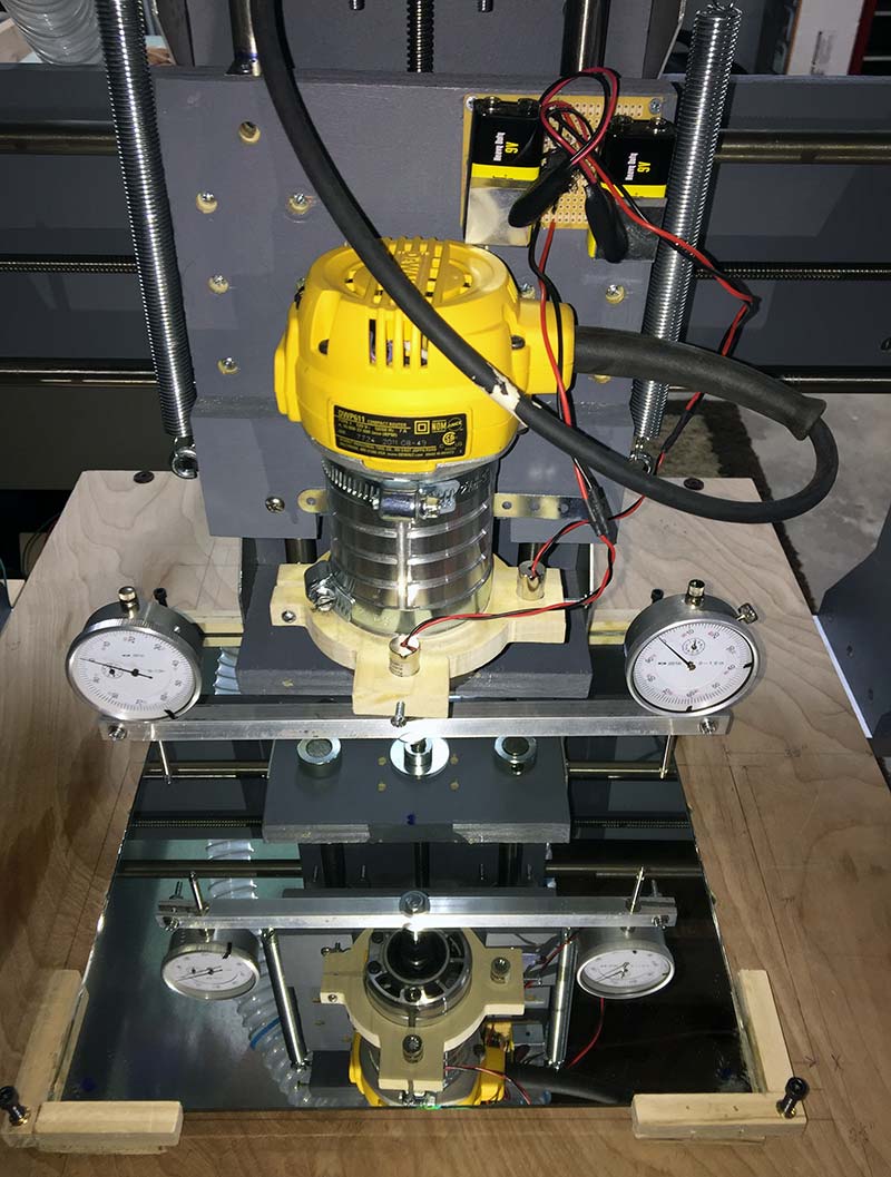
FIGURE 12.
Just like in the north/south test, both dial indicators must match readings in the east/west position for the motor to be correctly adjusted for tilt. If this is not the case, loosen the motor mounting bolts and rotate (tilt) the motor left or right until the motor is sitting perpendicular to the mirror.
You’ll know the motor is adjusted correctly when both dial indicators read the same number at the east and west positions.
FINAL NOTES
If this is your first experience tramming your router, don’t let the procedures in this article overwhelm you. Once you’ve completed all the steps, you’ll see the simplicity of the whole process.
If your CNC router gets a daily workout, tram your machine every two to three months. This is especially true if you start noticing an increase in broken tool bits or changes in the surface quality of your workpiece.
Finally, you might want to read the article I wrote on backlash for Nuts & Volts Magazine. Backlash can also have detrimental effects on the operation of your CNC router. SV
Parts List
| QTY | DESCRIPTION | PART# | SOURCE |
|---|---|---|---|
| MIRROR BRACKETS | |||
| 1 | 1/2” x 36” Square Dowel | n/a | Home Depot |
| 4 | #10-32 Insert Nuts, Brass | 483-946 | Home Depot |
| 4 | #10-32 x 1-3/4” Socket Head Screw | 90044A119 | McMaster-Carr |
| 1 | 12” x 12” Mirror or Glass | n/a | Home Depot |
| 1 | 1/4” x 12” x 12” Plywood | n/a | Home Depot |
| 1 | Epoxy Glue, .25 ml, J-B WELD | n/a | Home Depot |
| 16 | #6 x 5/8” Wood Screws, Flat Head Phillips | 282-265 | Home Depot |
| EXTENDER ARM FIXTURE | |||
| 1 | 1/2” x 1/2” x 12” Aluminum 6061 Flat Bar | AB2142 | Amazon |
| 2 | Triton 1” Dial Indicator, .001 Grad Travel | ALL-52000 | Amazon |
| 2 | 1/4” x 2” Hex Bolt | AFD | Home Depot |
| 2 | 1/4” Flat Washer | AAA | Home Depot |
| 2 | 1/4” Hex Nut | AAB | Home Depot |
| 2 | #6-32 x 1-1/4” Machine Screws + Nuts | 460-296 | Home Depot |
| 4 | #6 Flat Washer | 380-250 | Home Depot |
| 4 | #6 Split Lock Washer | 520-764 | Home Depot |
Article Comments