How I Make 3D Printed Parts
By Roger Secura View In Digital Edition
In this article, I’ll introduce you to the process and the free software I use to make 3D printed parts.
3D printers are great! You can go from an idea to a simple 3D printed part in about two hours. Even Amazon can’t beat that delivery time — yet! A short time after I bought my 3D printer, I noticed my thought process changed when it came to acquiring parts for my projects. Now when I need a part for a new design, I immediately ask myself, “Can I make this part on my 3D printer?” Fortunately — more often than not — the answer to that question has saved me a lot of time and shipping costs.
THE PROCESS
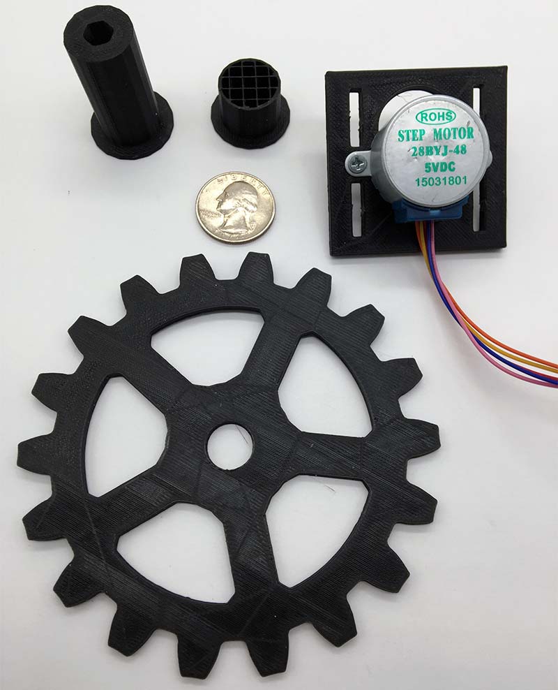
I should mention here that most of my CAD designs are simple 2D drawings (gears, mounting plates, standoffs, etc.). In other words, I’m not printing 3D Star Wars figurines; see Figure 1.
 .
.
FIGURE 1.
The flowchart in Figure 2 shows the entire process I use to create a 3D printed part.
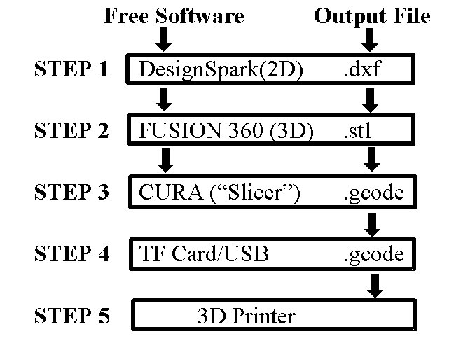
FIGURE 2.
STEP THIS WAY
Step 1: I prefer to use a CAD program that I’m familiar with to start the design process. I’m very familiar with AutoCAD software and the standard drawing file extensions (.dxf, .dwg, etc.). Unfortunately, the software is a little bit too expensive for my limited income, so I currently use a free (open source) CAD program called DesignSpark Mechanical (DSM).
Just like AutoCAD, DSM is fairly easy to learn and you can save a 2D drawing as a .dxf file or a 3D object as an .stl file.
I start the design process with a 2D sketch. The motor mounting plate I designed in Figure 3 is a good example. I always like to design a part in a one-to-one scale (1:1 or 1x). In other words, a one inch line in the drawing will equal one inch in the real world. That way, I don’t have to do any math to scale the drawing up or down (i.e., fewer mistakes).
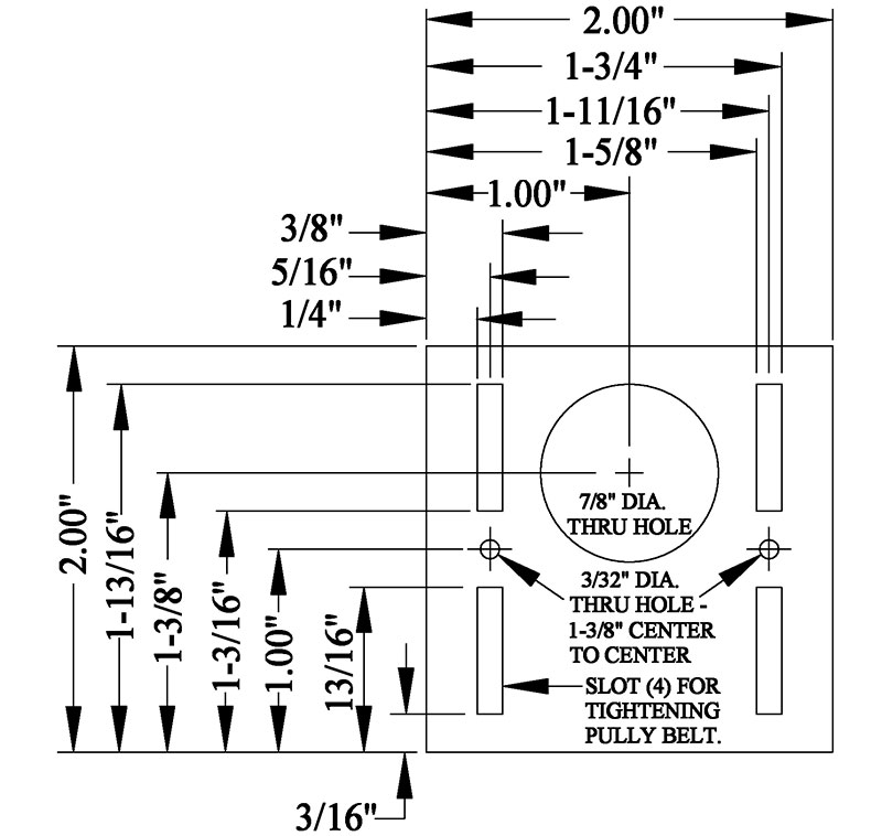
FIGURE 3.
Since it’s impossible to cover all the DSM design features in this article, here’s a very short tutorial on how to create a simple 2D drawing in less than three minutes.
To create a 2D drawing in DSM, select New and then Design from the File menu tab. A grid will appear on the screen showing the X, Y, and Z coordinates (see Figure 4).
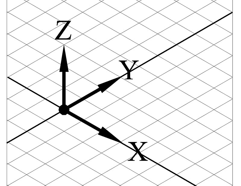
FIGURE 4.
Now, select Plan View (X, Y) from the Design menu tab. The grid will automatically orientate itself on the screen, so it appears as if you’re looking down at a piece of graph paper sitting on your desk (see Figure 5).
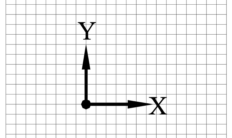
FIGURE 5.
Now, all you do is select the rectangle icon from the Sketch menu and then click your mouse one time at the XY junction point (0,0). You’ll notice as you drag the mouse to the right and upwards that a rectangle will appear. Just keep dragging your mouse to the right to resize the rectangle as needed, or enter a couple of values for the length and width into the dimension text boxes (see Figure 6).
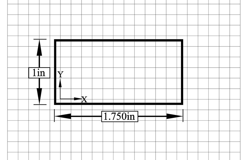
FIGURE 6.
If you add any dimensions to the drawing, it helps if you turn them off before saving your drawing. DSM uses an Annotation Plane check box instead of layers to turn off all the dimensions in a drawing. To access the check box, just select the Structure tab on the left side of the screen.
Finally, save your drawing as a .dxf file by clicking the File tab and then SaveAs on the menu bar. Next, select the dropdown text box labeled Save as Type and click on AutoCAD Files (*.dxf) from the list. Now, give the file a name and then hit the Save button. Your 2D drawing (rectangle) is now saved and ready to be converted into a 3D object (see Step 2).
Step 2: Next, I import the DSM .dxf file into a cloud-based program called Fusion 360. This is another free CAD program that can also create 2D and 3D drawings.
Unfortunately, I’m not a big fan of cloud-based programs. For example, I don’t like the fact you have to send your completed 3D drawing file (XXX.f3d) to the Autodesk cloud server before Fusion 360 can convert the drawing to an .stl file (3D printer file format).
I know I’m not designing parts for NASA, but I like to decide where my designs will reside.
On the other hand, Fusion 360 makes it very easy to turn a simple 2D drawing into a 3D object. All you do is select Insert and then .dxf from the menu bar; select a surface plane on the XY grid; grab a 2D .dxf file (rectangle.dxf) from your hard drive; select Extrude from the menu bar; select the top surface of the rectangle; and click on the blue arrow and pull (drag) it upwards (see Figure 7). Just remember to save the 3D object as an .stl file.
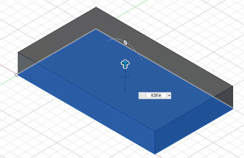
FIGURE 7.
Now, you may be thinking, why not just do the 2D/3D CAD work in Fusion 360 or DSM and then send the file (XXX.stl) to the 3D printer?
Obviously, the process I’m describing here is not the only way to create a 3D part. It’s just what I’m comfortable with right now. In the future, when I decide which CAD software package I like better (i.e., easier to use), I’ll eliminate Step 1 (DSM) or Step 2 (Fusion 360) from the process.
Step 3: Next, I import the 3D .stl file from Fusion 360 into a Slicer program to generate a .gcode file for my 3D printer.
Slicer programs like Cura (free open source) and Slic3r let you view, edit, slice (layers), and change 3D print settings before you send the final .stl or .gcode file to your 3D printer. Slicer software can save you from the pain of watching a two hour print fail.
The ability to manipulate 3D print settings is critical to the outcome of a 3D print. For example, fill density, filament thickness, print speed, layer thickness, and temperature are just a few settings that a good slicer program like Cura can control. For example, here are the basic Cura print settings I use for black PLA+ filament:
Alphawise U30 3D printer
Layer height = .2 mm
Shell thickness = .8 mm
Enable retraction = Yes
Bottom/Top thickness = .6 mm
Fill density = 20%
Print speed = 50 mm/s
Print temperature = 210°C
Bed temperature = 0
Filament diameter = 1.75 mm
Nozzle size = .4 mm
Fan speed = 255 (100%)
Step 4: Finally, I verify that all my Cura print settings are correct. Next, I select Save GCode from the Cura File menu and save the file (XXX.gcode) to a TF card (microSD card). Of course, the TF card is not the only way I can transfer files to my 3D printer.
I just don’t have my laptop computer connected (USB cable) to my 3D printer.
Step 5: Now, all I do is go down to the basement and slide the TF card into the slot in the back of my 3D printer and print. Done!
(Warning: TF cards are about the size of your baby fingernail. Try not to sneeze or cough while working with TF cards or you’ll never find that card again in your lifetime.)
PRINTING TIPS
• It’s absolutely critical that you level your build plate! A number of printing problems can be traced back to bed leveling; for example, the first layer of filament not sticking to the build plate.
The photo in Figure 8 is a close-up view of one of the four small thumb wheels I use to adjust the level of my build plate.
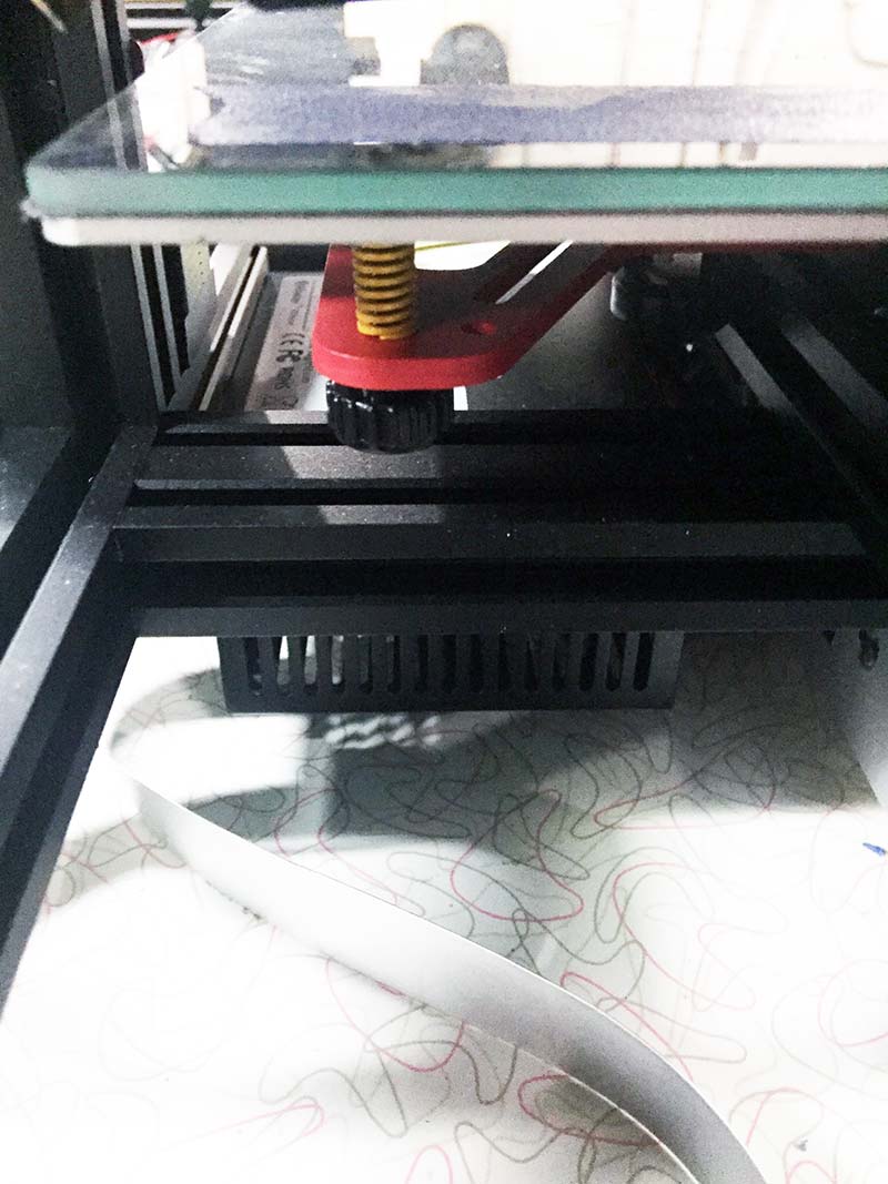
FIGURE 8.
As a preliminary step, I prefer to use a small level (see Figure 9) to get the build plate as close to level as possible on the X and Y axes.
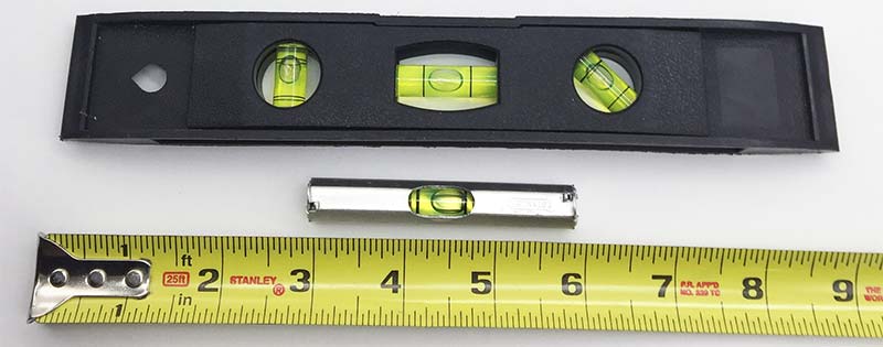
FIGURE 9.
As a follow-up leveling procedure, I use the old “paper” leveling method. The procedure is fairly simple, but beyond the scope of this article (check YouTube).
I guess the ultimate solution would be to use a Dial Indicator (thousandths of inch accuracy). I just haven’t figured out how to mount a dial indicator onto my 3D printer.
• Another problem you’re likely to encounter is getting the filament (PLA, ABS, etc.) to adhere to the build plate (glass plate). There are many ways to solve this problem, and it really depends on the type of filament you use. Aqua Net hair spray, blue painter’s tape, glue, and “ABS juice” (ABS and acetone) are just a few methods you can try.
I’ve found putting down a few rows of blue painter’s tape on the build plate and then applying (with a paper towel) a very thin coat of Elmer’s Glue (see Figure 10) works great with black PLA+ (PolyLactic Acid) filament. Just make sure the print temperature is set to 210°C. Also note that PLA filament usually doesn’t require a heated bed.
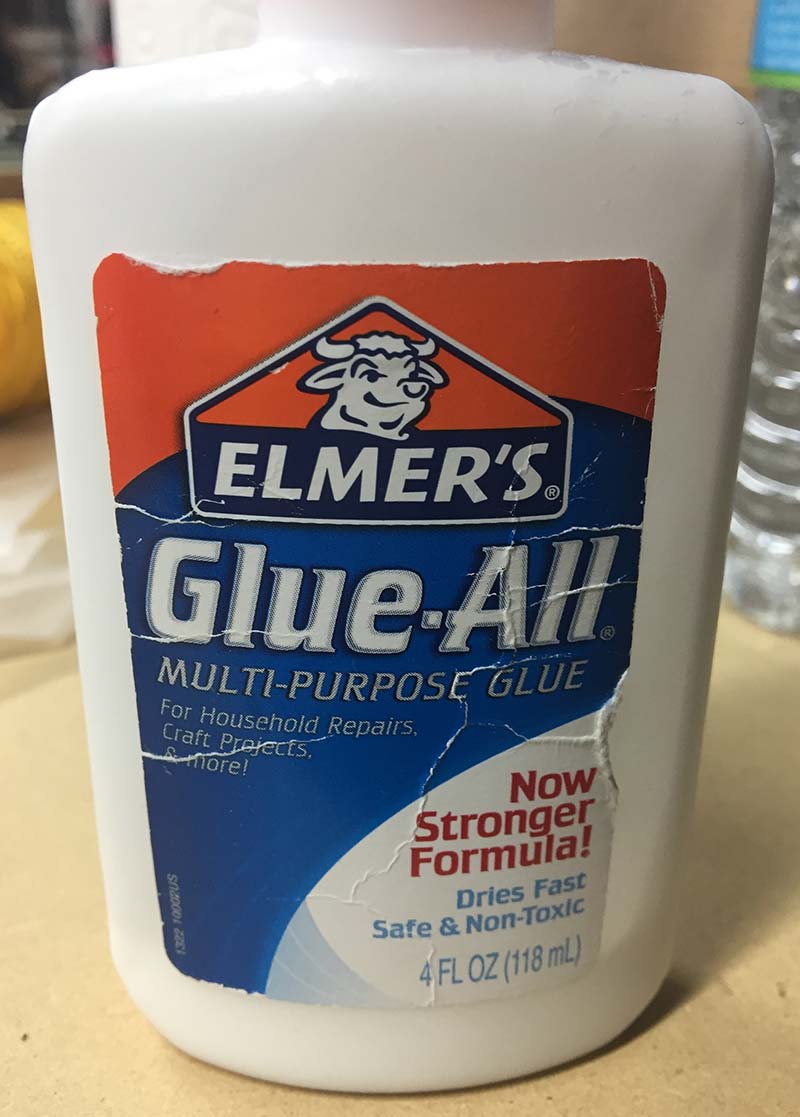
FIGURE 10.
• If you’re new to the world of 3D printing, I suggest using PLA as a starter filament. Since it’s basically made from sugarcane and cornstarch (biodegradable), it’s one of the least toxic of all the filaments you can buy. On the other hand, if you want to experiment with a different type of filament, I suggest you build a vented enclosure for your 3D printer. Save your lungs!
• Pay particular attention to the Fill Density setting in Cura. This setting determines how dense the filament material (PLA) will be for the interior structure of your part. The percentage of fill density you select can have a dramatic effect on the rigidity of your printed part, the amount of filament required, and the length of time to print.
A good starting point for PLA filament is a 20% fill density. This is a good compromise between part strength, filament usage, and printing speed. Raise or lower the percentage as needed.
• Under- or over-sized filament diameter can also ruin a 3D print. Filament diameter varies from manufacturer to manufacturer. Use a digital caliper and measure the filament diameter a few places along the reel. Take an average and use that value for the filament diameter setting in your slicer program (Cura).
• If you don’t want to crack or warp a two hour print, let your heated bed and 3D object cool down (harden) for about 5-10 minutes before removing it from the build plate.
• To make the print removal process easier, get some good tools for removing the 3D objects from the build plate surface. It’s nice that glue helps the filament stick to the build plate, but removing the printed part can be a real pain somewhere around the lower extremities.
Figure 11 shows a couple of tools I use to slide underneath a part that’s stuck to the build plate. You can find a ton of similar spatulas/putty knifes on Amazon.
Lifting parts off the build plate is easier if you don’t try to pry upwards on the part. Just move the knife from side to side (wiggle) while at the same time putting forward pressure underneath the part. Work your way around the part so it’s released evenly from the build plate.
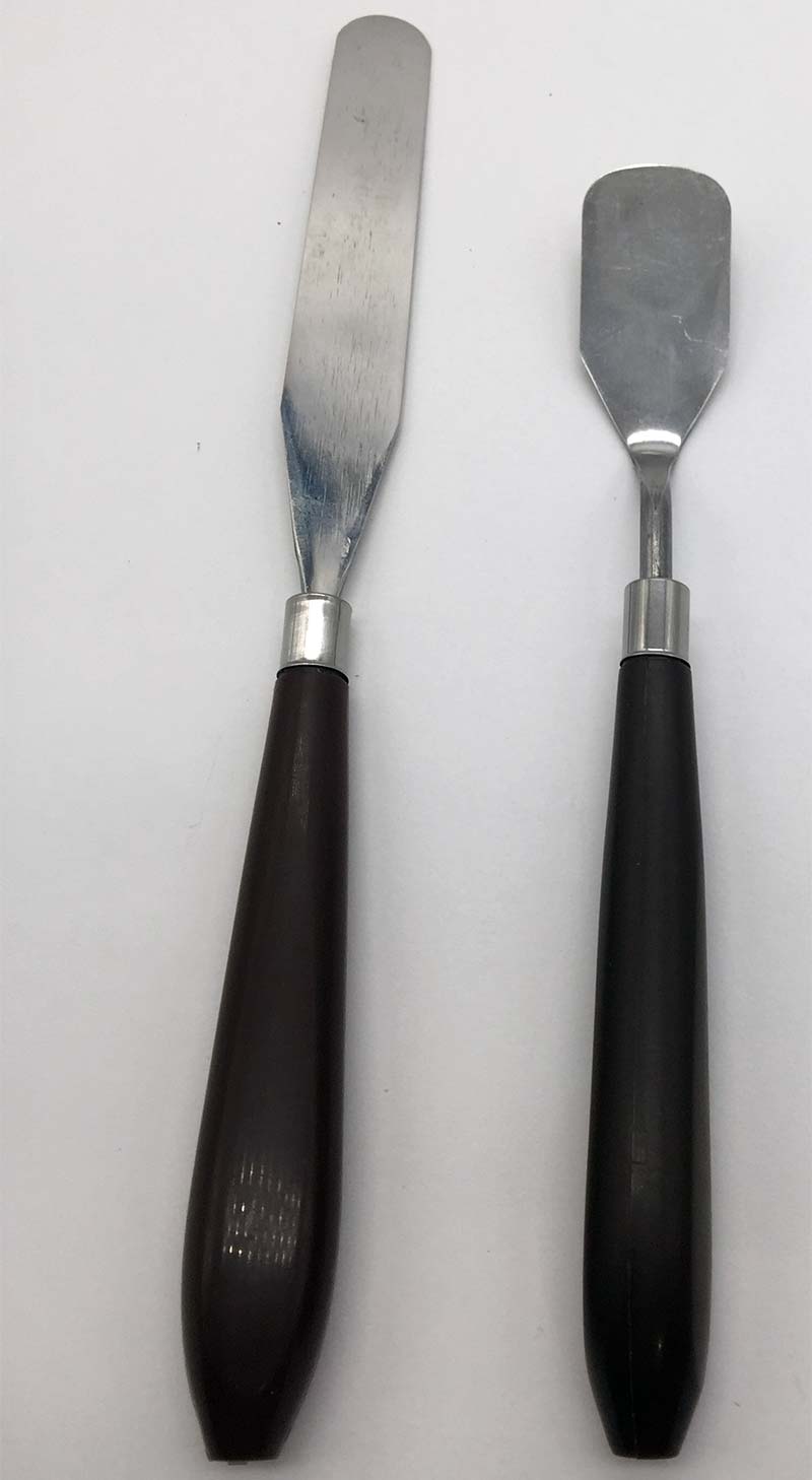
FIGURE 11.
FINAL WORD
When you think about it, all we did here is create a 2D drawing, extrude the drawing into a 3D object, adjust a few print settings in Cura, and then load the .gcode file into the 3D printer.
The only hard part in the whole process is learning how to use both the CAD and Slicer software. SV
Article Comments