Embedding the RobotBASIC Robot Operating System into the Parallax Scribbler S3
By John Blankenship View In Digital Edition
Parallax’s Scribbler S3 may be one of the most overlooked and underrated robots on the market. Right out of the box, it has line sensors for following lines, perimeter IR sensors for detecting obstacles, light sensors capable of isolating the brightest light in a room, and wheel encoders that make accurate movements possible. Adding a few sensors through the hacker port gives it more sensory capability than most hobby and educational robots. Embedding a custom version of the RobotBASIC Robot Operating System makes it one of the easiest robots to program.
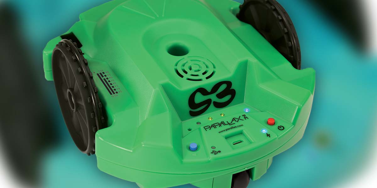
In the December 2017 and January 2018 issues of SERVO, two articles demonstrated the power of the RobotBASIC Robot Operating System (RROS) by showing how it simplifies building and controlling robots. Another article in February 2018 showed how the S3’s hacker port can be used to expand the robot’s sensory capabilities. This article combines all these ideas by embedding a custom RROSS (RobotBASIC Robot Operating System for the Scribbler) inside the S3 (Figure 1 Lead photo above).
The RROSS makes it extremely easy to control the S3’s movements and to utilize the standard S3 sensors from RobotBASIC (a free language available from www.RobotBASIC.org). This eliminates many of the shortcomings of other languages for the Scribbler. With RobotBASIC, your programs can use integers, floats, and strings for simple variables (both local and global) and multidimensional arrays. You can use both 2D and 3D graphics, as well as GUI features like buttons and sliders to enhance the user experience with your programs. Furthermore, you’ll have a full range of debugging capabilities and hundreds of specialized functions that simplify complex tasks.
RobotBASIC’s integrated robot simulator allows you to develop algorithms and even complete programs in a controlled environment, and then use them with minimal modification to control the S3. A welcome feature is that programs do NOT have to be downloaded to the S3. Just write your code, click RUN, and the S3 immediately responds.
For many robot hobbyists and schools, this is an ideal combination — especially since the S3 comes fully assembled and ready to use. RobotBASIC needs to communicate with the embedded RROSS though, so at a minimum, a Bluetooth transceiver must be added. The unit shown in Figure 2 is readily available on eBay.
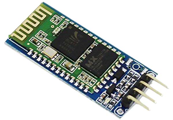
Figure 2.
It can be attached to the S3 with double-sided tape as shown in Figure 3.
Power for the transceiver is available on the hacker port. The TXD and RXD (transmit and receive) pins on your Bluetooth device should connect to hacker port pins P0 and P1, respectively.
Let’s explore how easy it is to write RobotBASIC programs for the S3. Look at the small program in Figure 4 which produces the output shown in Figure 5.
gosub DrawObjects
rLocate 400,500,random(360)
rInvisible GREEN
rPen DOWN
while TRUE
d = rFeel()&14
if d = 8
rTurn 45+random(30)
elseif d = 2
rTurn -(45+random(30))
elseif d = 4
rTurn 160+random(40)
else
rForward 1
endif
wend
DrawObjects:
rectangle 150,150,250,200,RED,BLACK
rectangle 500,200,600,400,RED,BLACK
circle 250,400,350,500,RED,BLACK
return
Figure 4.
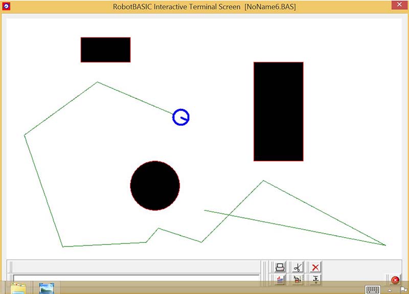
Figure 5.
The program begins by drawing three obstacles on the screen and initializing the simulated robot at pixel position 400,500 at a random orientation. A pen is dropped to leave a GREEN trail as the robot moves. The color green is made invisible so the trail will not appear as an object to the robot. If you want to know more about any command, RobotBASIC comes with a 300 page HELP file.
The simulated robot has five feel sensors as shown in Figure 6. The S3 has only two IR sensors to detect obstacles in front of the robot. The RROSS maps this information into RobotBASIC’s rFeel() function as follows.
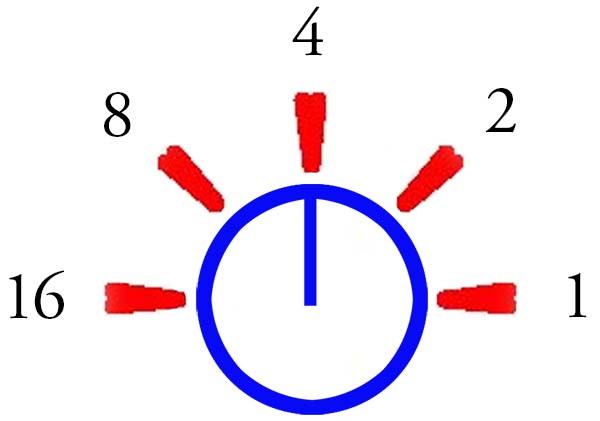
Figure 6.
If the S3 detects an object on its right, sensor position 2 is activated. Objects on the left activate position 8, and if both sensors detect an object, position 4 indicates something is probably directly ahead. This is especially true for the S3 because the entire IR beam detection area is very narrow.
For the simulator to more accurately mimic the S3, we must ignore feel positions 16 and 1 by forming a binary AND with 14 (8+4+2). Depending on the final sensor value, the program turns the robot randomly to the right or left, or a complete about-face. If no sensors are active, the robot simply moves forward. As you can see from Figure 5, this moves the robot around its environment in a random motion.
Controlling the S3
We can use this same program to control the S3 by simply inserting the statement rCommPort 5 to the very beginning of the program. Note: Use the port number for your Bluetooth port instead of the 5 shown. That’s it! The S3 will roam around its environment just like the simulation.
Since the S3 has a hole for a pen, it can leave a trail if you have a large paper or whiteboard. Figure 7 shows the real robot moving randomly on a small whiteboard.
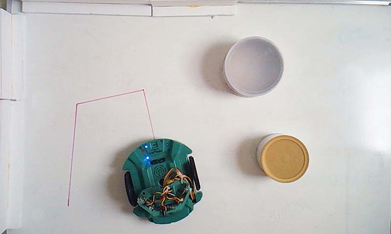
Figure 7.
The walls in the figure can easily be made with foam board. The round obstacles were made from cut-down oat boxes. Imagine a 4x8 foot whiteboard (available from Lowes and Home Depot) serving as a customizable project space for schools and/or robot clubs.
Possible Collisions
When the simulator uses all five of its sensors, it works perfectly. When using only the three middle sensors, its limited peripheral vision makes it possible (though not likely) to collide with objects slightly left or right of the sensor detection area.
As expected, this is also true of the S3.
A Multiple PING))) Enhancement
Adding three PING))) sensors (ultrasonic rangers from Parallax) to the S3 provides a much larger scanning area. This improvement is due to the broad ultrasonic beam (compared to IR) and the wider orientation of the sensors.
In most cases, this augmentation can eliminate collisions, but it also allows the S3 to scan to the left and right while moving forward. This makes behaviors like autonomous navigation and wall following possible.
You can make your own PING))) mount or even just hot-glue the PING))) sensors to the S3. However, the 3D printed mount in Figure 8 (available from RobotBASIC) complements the S3 nicely.
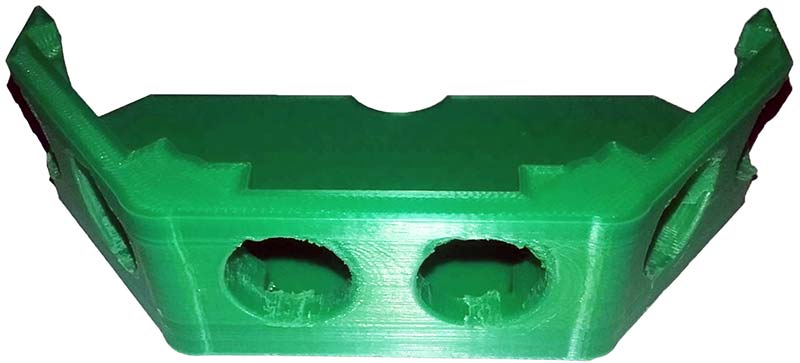
Figure 8.
All electrical connections can be made with standard cables, so no soldering is required as shown in Figure 9.
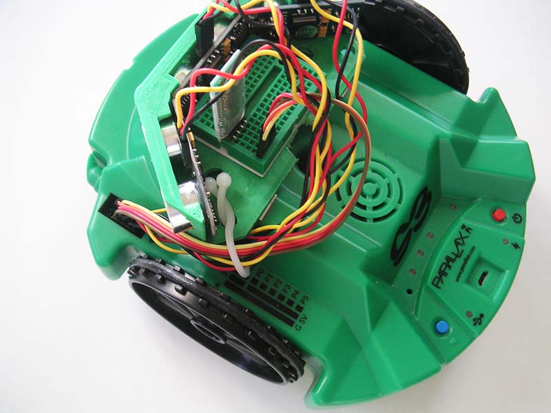
Figure 9.
A Virtual Sensor System
The addition of the PING))) sensors allows the RROSS to implement a Virtual Sensor System (VSS). In addition to each ranger being individually accessible with rRange(), digital proximity information can be accessed with the functions rFeel() and rBumper(). Each bit returned by these functions indicates when a specific sensor sees an object within a user defined range.
This is a massive improvement over the S3’s standard IR sensors. The RROSS even gives you the option of merging the S3’s native IR data with the PING))) readings. This can improve reliability because various objects can absorb — rather than reflect — IR (dark objects) and ultrasonic signals (soft objects).
Easy Access to Native S3 Capabilities
In addition to the ranging and perimeter proximity sensing, RobotBASIC provides functions for accessing the S3’s light and line sensors. You can even command the S3 to play tones or move in specific arcs. Programming an S3 could not be easier.
Beacon Detection
For those wanting more, the RROSS supports the RobotBASIC beacon technology allowing the S3 to detect up to eight distinct beacons. The beacon detector is shown in Figure 10. It’s composed of a black tube (increases the directionality of the detector) hot-glued to a Vishay TSOP341 IR sensor.
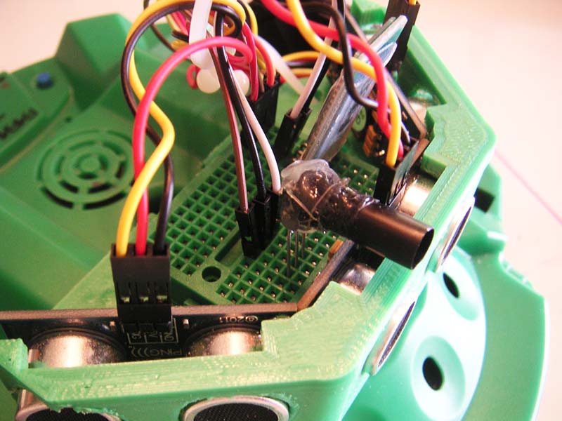
Figure 10.
Open Source Code
The RROSS code is open source and available in the article downloads and also from RobotBASIC and Parallax. Since the RROSS is written in Parallax’s BlocklyProp, it should be easy for advanced users to customize everything to meet their specific needs.
The standard Parallax Scribbler S3 has capabilities that deserve your consideration, and with a few extra sensors and a RobotBASIC interface, it really stands out. SV
Article Comments