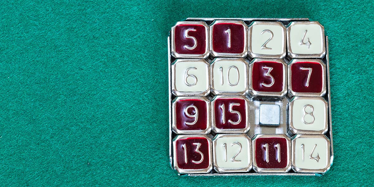
Can PuzzleBot Solve a Sliding Number Puzzle?
By David Goodsell, Matt Borack View In Digital Edition
Do you remember those little 4x4 plastic sliding puzzles numbers 1 to 15? Do you think a tabletop robot arm could solve them as easily as your fingers? We’ll see.
When I was a kid, I carried one of these puzzles around in my pocket and had fun solving it. It came in a little cloth pouch with a card showing other configurations to solve (Figure 1).
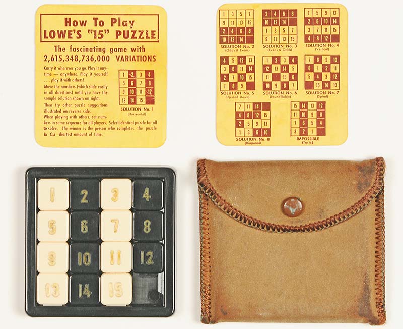
Figure 1: The vintage “15” sliding puzzles made by both Lowe and Steiner came in cloth pouches with cards showing other ways to solve the puzzle.
The original puzzles are still available on eBay, plus Amazon sells similar modern versions but they aren’t half as good.
Several months ago, I bought a Dobot Magician robot arm and had been looking for something for it to do. Figure 2 shows it trying to earn its keep by solving a vintage 4x4 sliding puzzle.
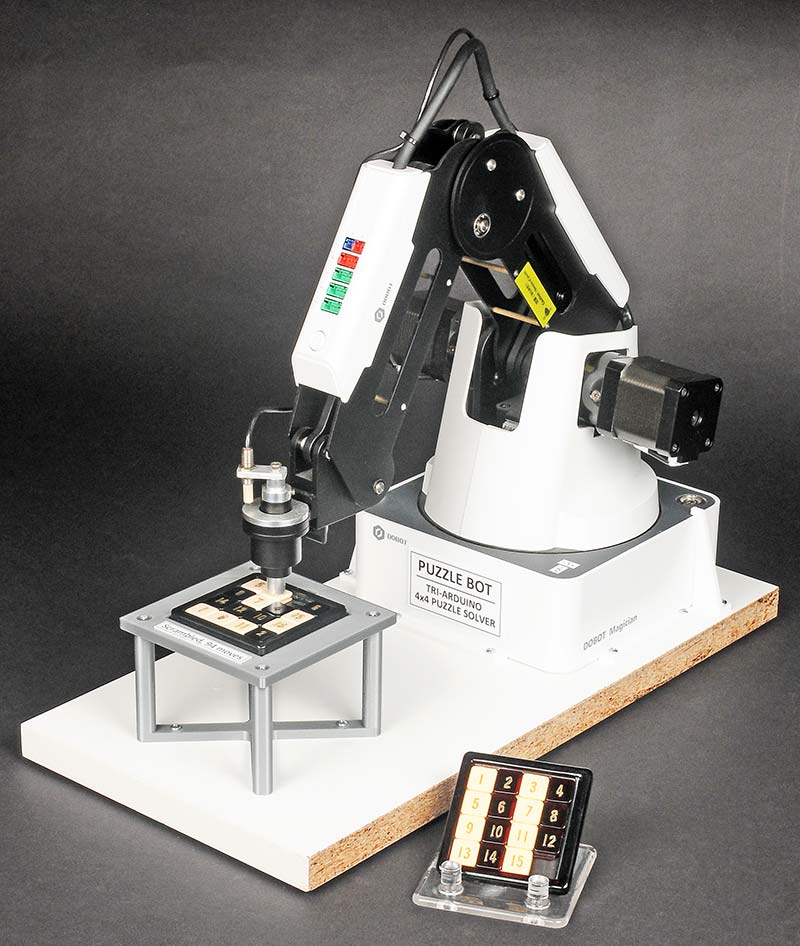
Figure 2: The Dobot Magician tabletop robot arm can solve the puzzle in a little over three minutes. The record for humans is 5.18 sec, using the larger magnetic Klotski puzzle from Amazon.
The first step was seeing if the arm could move the little numbers without slipping or tearing up the puzzle. The Dobot came with an end effector that could hold a pen as shown in Figure 3.
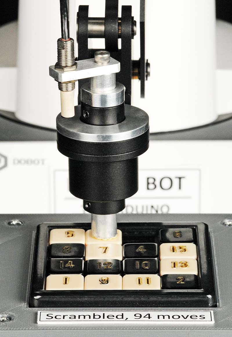
Figure 3: The stylus presses down on the numbers with a tiny piece of rubber to slide them.
Instead, I slipped a small aluminum rod (stylus) in place of the pen and glued a little piece of soft eraser on the end. Ready to go!
Result? Not good! The eraser was too slippery. It just slid across the plastic numbers, only moving them a little.
Next, I tried a little piece of sticky tape on the end. Worse. Much too sticky! It almost pulled the numbers out of the frame. Then, I found a kitchen rubber glove that had little bumps on it. Wow! It worked great! Just enough friction but not too much.
The pen holder was spring-loaded, so I didn’t have to worry about it putting too much pressure on the puzzle pieces.
MOVING THE ARM
I found an Arduino sketch written by the Dobot people that could send “move” commands to the Dobot. However, there was definitely a learning curve to get the arm to do what I wanted. The program was obviously written by professional programmers, meaning that some of it went right over my head.
After a while, I learned how to format and insert my own commands in amongst all their modular programming. That was the first step in a several months’ long struggle to build a complete working system.
THE FINAL SYSTEM AND A VIDEO OF IT WORKING
Figure 4 shows the final system with the Dobot, three Arduino Megas, one Raspberry Pi, a Raspberry Pi camera, an LED photo light, and a large 32x32 LED display.
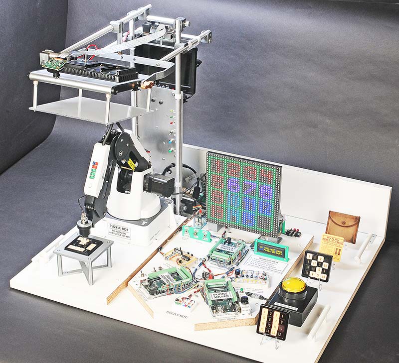
Figure 4: The PuzzleBot uses four small computer boards to control the robot arm. A 32x32 LED matrix displays the locations of the numbers as they are moved.
Figure 5 shows the RasPi camera focused down on the puzzle.
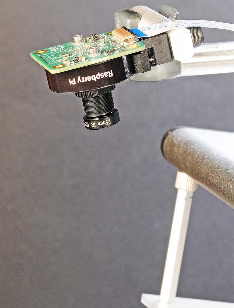
Figure 5: A Raspberry Pi camera and LED photo light capture a single image of the puzzle to determine the starting positions of the numbers.
Figure 6 is a typical camera image ready for processing.
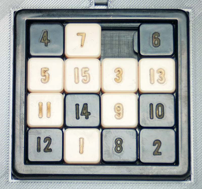
Figure 6: Using a diffused light source produced a suitable image with good contrast for analysis.
A schematic of the whole system is shown in Figure 7.
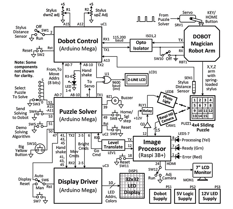
Figure 7: A Raspberry Pi 3B+ (image processor) dissected the image and sent the results to the Puzzle-Solver Arduino via a serial port.
In operation, the camera takes a single image of the puzzle, and the Raspberry Pi computer-vision program determines where the 15 numbers are initially located. The locations are transmitted to the Puzzle-Solver Arduino which, in turn, decides which moves to make to solve the puzzle. The moves are sent to the Dobot Control Arduino one by one and the Dobot arm physically moves the little pieces.
As the Dobot moves the pieces, the changes are updated in memory, so, technically, it always knows where the numbers are located and which move to make next.
After some sleepless nights of debugging, the PuzzleBot worked great and was able to reliably solve a typical scrambled puzzle in three and a half minutes with 86 moves. Not nearly as fast as a human, but it was fun to watch. Perhaps in the future, I’ll speed up the Dobot and see just how fast it can really go. For now, I didn’t want to break anything.
BTW, I love the Dobot! It’s as accurate and reliable as I could have wanted. I put it through thousands of cycles, and it just kept on goin’.
You can see the PuzzleBot system in action at https://youtu.be/Ht1gYLNpdDk. (Note: The character after the ‘Ht’ is a ‘one’ not a lower case ‘L.’)
HOW DOES THE DOBOT KNOW WHERE THE NUMBERS ARE?
Initially, the PuzzleBot didn’t have a camera to determine the starting setup of the puzzle. My nephew, Matt (a computer programmer), took one look at the unit and wondered how it kept track of the numbers as it moved them around — especially since he didn’t see a camera looking down at the puzzle.
I told him that I had to type in the initial locations of the numbers and from then on, the Dobot kept track of their positions in memory as it made each move. He felt that instead of initially typing in the numbers, the process could be automated by using a camera, since he had previously used an OCR (Optical Character Recognition) API on another project.
So, I mounted an LED photo light and Raspberry Pi camera above the puzzle and sent him an image of it (refer back to Figure 6). We live about 50 miles apart.
MATT RECALLS: HOW I SOLVED THE IMAGE PROCESSING CHALLENGE
I thought my part would be a slam dunk. Grab the image, call an OCR API in the cloud, and be done. Boy, was I wrong. It turns out the quality of the lettering seen in the image that Dave sent me caused a lot of issues. For example, the fading gold-colored numbers on an off-white background and a font that has the digits 6 and 8 looking so similar made it trickier.
These issues resulted in misidentification or nothing being identified at all. Dave spent time improving the quality of the images and finding better game boards, but in the end, I felt I had to try a different approach.
I chose image matching due to the fixed setup, the limited number of blocks (15), the fixed game board, and consistent lighting conditions. Image matching wouldn’t have been a good option in a non-fixed setup, like someone holding the game board. Since this approach requires comparing each numbered block to the given game board image, I manually sliced a sample game board image to produce one image per numbered block (Figure 8)
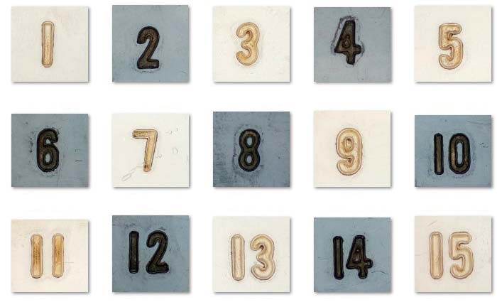
Figure 8: The image processing software used OpenCV (Open Computer Vision Library) to match the 15 stored blocks to the camera image.
With two copies of Microsoft Paint open, the whole process took a few minutes and only needed to be done once.
OPEN CV2 AND NUMPY DO THE MATCHING
I began writing my image matching code by using the first code sample at https://www.geeksforgeeks.org/template-matching-using-opencv-in-python/. It’s written in Python and uses the OpenCV and NumPy libraries. The image matching is done with the matchTemplate() function in TM_CCOEFF_NORMED mode. I found most other modes were too slow for the Raspberry Pi, even running at 1.4 GHz; this line takes most of the total runtime. I wrapped a loop around this to iterate over the 15 numbered blocks.
For each numbered block, the result of calling the matchTemplate() function is reviewed and the best matches are kept. These matches contain boundary information which is used to draw boxes on a copy of the board game image.
Next, the matches are checked if they’re fixed to one area or not; if not, then a warning message is shown.
As each numbered block is processed, the returned matches data is added to the running results and an attempt is made to determine how they are positioned relative to each other.
This newly determined positional information is sent to the serial port where it’s shown on the 32x32 display, one iteration at a time.
It takes around 63 seconds to identify all 15 locations of the numbered blocks. The blank area is given the value 16.
You can watch the whole iteration process in the video at https://youtu.be/Ht1gYLNpdDk.
Actually, there are ways to make the identification even faster, but Dave wanted the process to be slow enough to be easily followed on the display. I broke out the code into multiple files. The file names are self-explanatory and the “main.py” file is where everything starts. I left in the commented-out debugging statements to help should you need them.
BACK TO DAVE: WHY AM I USING THREE ARDUINOS TO CONTROL THE DOBOT?
That’s a good question. The basic answer is that I soon realized that I would have a hard time keeping track of the three different major functions if they were all on one Arduino. I knew the software would eventually involve thousands of lines of code and a googolplex of modules, and that I would spend 90% of my time keeping track of which function was doing what. So, splitting up the tasks led to three Arduinos talking to each other via serial and parallel I/O lines (Figure 9).
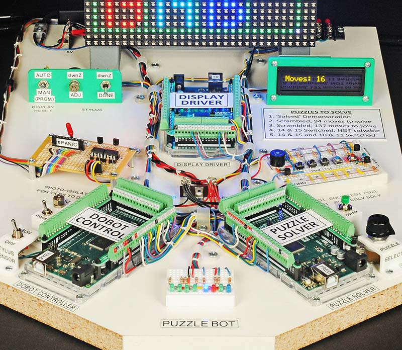
Figure 9: Three Arduino Megas divided up the tasks of puzzle solving, Dobot control, and driving the display. There were 1,649 possible moves programmed in the puzzle-solving Arduino.
Maybe I could have used Unos, but I like Megas because they never run out of pins. The Arduino tasks are described next.
- The Puzzle Solver Arduino, which I wrote from scratch, ended up with over a thousand lines of code that frankly got out of hand, but it works! Matt’s RasPi sends the initial puzzle locations to this Arduino via a serial port.
- The Dobot Control Arduino contains a bunch of .cpp and .h modules written by the Dobot people. It communicates directly with the Dobot. I just added to their code.
- The Display Driver Arduino uses an Adafruit 32x32 LED driver library that was ready to go. It required 10 Arduino pins to control the display.
SOLVING THE PUZZLE
Of course, I knew how to solve the puzzle with my fingers, but I needed to find or write a program to guide the Dobot. The Internet was full of discussions about how to solve sliding puzzles, even larger ones than my little 4x4. Some people used high-level algorithms to plot the moves. Very academic, but they required Gigabytes of memory to run them. Too complicated for an Arduino. I decided to do it the easy way, at least for me. I would develop several arrays that listed every single move that led to the end, starting with moving number 1 to the upper lefthand corner, number 2 to position 2, number 3 to position 3, etc.
Actually, the whole solving program was just a simple STATE machine. It checked the present STATE of the numbers, found the matching STATE in an array, and, in turn, told the Dobot which move to make. Check, match, move … check, match, move … repeat dozens of times. Done.
In some instances, where a series of moves were predictable like solving the corners, it was more efficient to program in a series of discrete moves instead of solving it one move at a time. In the end, I counted the number of moves that I had to figure out and typed them into the sketch in order to solve all the different configurations. It was 1,649 moves. Not too bad! Took me a week or so.
Figure 10 shows the general solving sequence that the Puzzle Solver Arduino uses.
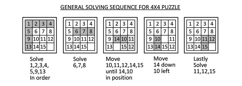
Figure 10: The puzzle is more easily solved by following a certain sequence. A video is available at https://youtu.be/Ht1gYLNpdDk.
Figure 11 illustrates a “rotational” technique to solve the pesky corners, which are the trickiest.
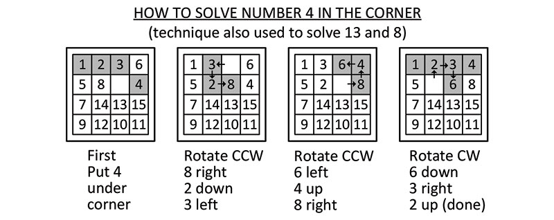
Figure 11: Solving the corner numbers (4, 8, and 13) is tricky but not that hard if you use a “rotation” technique.
Figure 12 illustrates the colors of the 32x32 display that highlight the solving sequence.
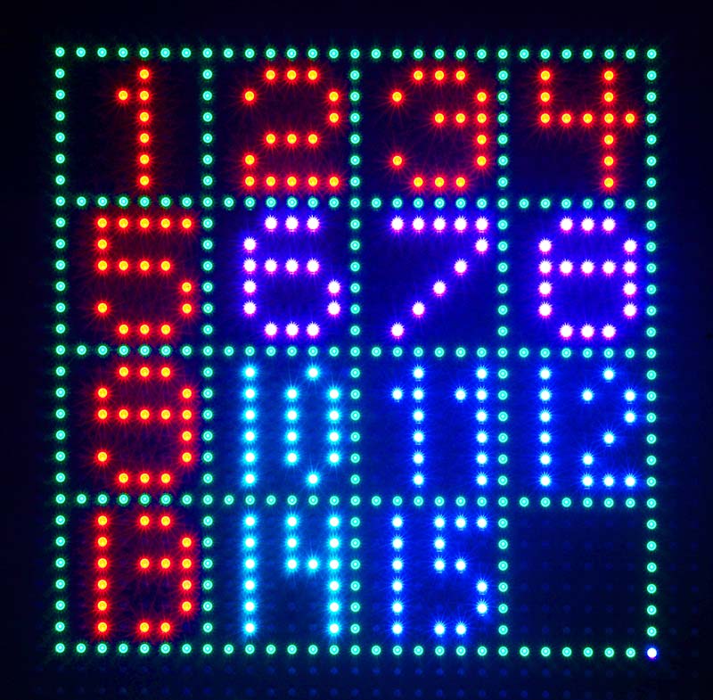
Figure 12: The different colors of LEDs on the 32x32 display illustrate the best solving sequence: red, purple, blue.
First red, then purple, light blue (10,14), and finally blue (11,12,15). BTW, the Internet has a plethora of videos showing how to solve these puzzles in several different ways. Your choice.
32 x 32 LED DISPLAY
I love the 32x32 LED display because the biggest problem in writing the solving code was checking for bugs. I decided to make an electronic 4x4 puzzle display using a SparkFun 32x32 LED matrix and Adafruit library. That allowed me to see each and every move. Plus, it would graphically show people what the Dobot arm was doing as it moved the pieces. Dual purpose!
The bugs were usually due to “operator error,” like inverted digits in an array or just plain wrong moves in some cases. After several days of debugging, I finally got it all working. Zowie! It was a major miracle.
$1000 REWARD FOR SOLVING SAM LOYD’S PUZZLE
Question: If by chance some of the plastic number pieces accidentally fall out of the puzzle frame, can you put them back in, in just any order?
Answer: No! Some arrangements of the numbers can never be solved, according to number theory. The safest way is to put them back is in the normal order, one to 15, starting at the top left. Wikipedia has a great article called the “15 puzzle” that explains which arrangements are solvable and which are not. It’s kind of complicated ...
Which brings us to Sam Loyd. In the 1800s, Mr. Loyd offered a $1000 reward to anyone who could solve his particular “14-15 Puzzle” shown in Figure 13.
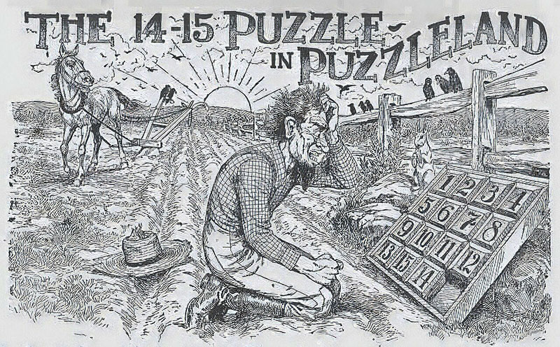
Figure 13: In the 1800s, a $1000 reward was offered to solve this mathematically impossible puzzle and nobody collected it. Notice the 14 and 15 are reversed.
You might notice that the 14 and 15 pieces are reversed, 15-14. Even though the mathematicians of that era had proven that it could never be solved, it became a national craze.
People had fun with it because of the reward, but since the reversed 14,15 arrangement was unsolvable, the $1000 went unclaimed.
PROBLEMS AND SOLUTIONS
Problem 1: The Dobot needed to go to its HOME position at the start to calibrate the arm.
Solution: The Dobot IDE (integrated development environment) had a graphic HOME button, but it would be nice if the Arduino was able to command it instead of having to connect it to a PC.
Frustration: I read the Dobot manual(s) and tried all kinds of commands to trigger a HOME, but it escaped me. I would welcome any advice on the exact Arduino code to use.
RC Servo Resolution: So, I resorted to a clunky but effective method. I mounted a small RC servo (Figure 14) on the rear panel of the Dobot and had it push on the KEY button, which triggered the HOME function.
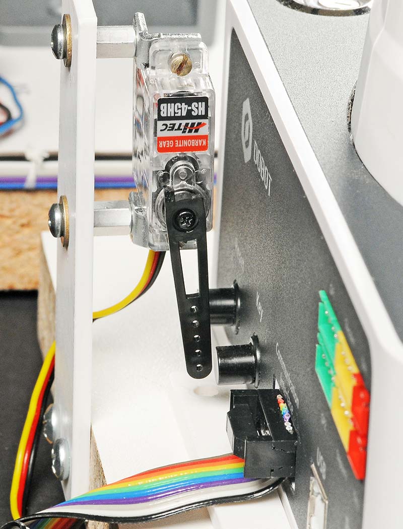
Figure 14: A small servo was used to press the KEY button to start the Dobot rotating to its HOME position for calibration.
Press, hold for three seconds, and release!
Alert: The button MUST be pressed for at least two seconds by the servo or the Dobot goes bonkers.
Problem 2: As you know, connecting individual wires to an Arduino Mega or Uno involves shoving them into the headers. It works but sometimes I worry.
Alternative Method: Several companies offer add-on screw-type terminal strips that fit on the headers. I selected one style that looked interesting (Figure 15) and installed three of them.
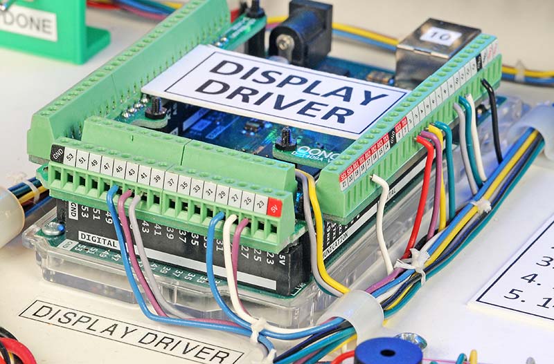
Figure 15: Connections were made to the three Arduinos using after-market screw terminals. They work very well.
Pros: Easy to read labels! Sturdy connection for wires. Terminals do not hide the Arduino printed circuit board.
Cons: $28/set. Fairly delicate, require a light touch.
PARTING WORDS
Hope you enjoyed this article. Matt and I had fun(?) solving the problems that arose. The Arduino sketches and Python code can be found in the article downloads. And don’t forget the associated video at https://youtu.be/Ht1gYLNpdDk. (Note: The character after the ‘Ht’ is a ‘one’ not a lower case ‘L.’
If you have any comments, please add them to the Comments section on the N&V website on my article page. For detailed questions, please contact me directly at dsgoodsell@verizon.net in Apple Valley, CA. I will pass along any image processing questions to Matt. SV
| Designator | Qty | Component | Source |
| R1,R2 | 2 | Resistor, 10K Pot, Locking, Allen-B | Personal NOS |
| R3-R6 | 4 | Resistor, 3.9K | 3.9KQBK |
| SW1,6,10,12 | 3 | Toggle Switch, Miniature, SPDT | Jameco 2135857 |
| SW2,4,5,7,8,9,11 | 6 | Pushbutton, Tactile, SPST | Jameco 153252 |
| SW3 | 1 | Switch, Rotary, 10 Pos, One Pole | Grayhill, Personal NOS |
| SW13 | 1 | Switch, SPST, Arcade Button | Adafruit 1186 |
| LED1-LED7 | 7 | LED, 3 mm, Various Colors | Misc |
| LED8 | 1 | LED Photo Light | B&H GVM 800D-RGB |
| DISP1 | 1 | 32x32 RGB LED Matrix, 5 mm Pitch | Adafruit, SparkFun |
| PS1 | 1 | Power Supply, Dobot, 12V, 6.7A | Dobot |
| PS2 | 1 | Power Supply, 5V, 7A, TDK LS35-5 | 285-1897-ND |
| PS3 | 1 | Power Supply, 12V, for Photo Light | B&H GVM 800D-RGB |
| Q1,Q2 | 2 | Transistor, NPN, 2N3904 | 2368-2N3904-ND |
| Q3 | 1 | Transistor, MOSFET N-CH & LEV1 Below | IRLF34NPBF |
| LEV1 | 2 | Level Converter, 3.3-5V, Four-Channel | SparkFun BOB12009 |
| ISO1,ISO2 | 2 | Opto-Coupler, 6N136 and Drivers | 6N136IS-ND |
| U1 | 1 | Neg OR Gate, Discrete Parts | Stock |
| uC1-3 | 3 | Arduino 2560 Mega, Microcontroller | Misc |
| uP1 | 1 | Raspberry Pi 3B+ Microprocessor | Misc |
| TERM1-3 | 3 | Screw Term, Mega, OONO MD-D1409-1 | Amazon $28/set of three |
| LCD1 | 1 | Two-line x 16 LCD Display | Seetron BPI-216N/L |
| CAM1 | 1 | Raspberry Pi HD Camera, 25 mm Lens | SparkFun SEN-21333 & 34 |
| MON1 | 1 | LCD Monitor, 7”, HDMI | Adafruit 1667 |
| BZ1 | 1 | Buzzer, 5V, 2300 Hz, TDB05LFPN | Jameco 76065 |
| SEN1 | 1 | Position Sensor, Kaman KD-2300 | Personal NOS |
| SRV1 | 1 | RC Servo, HItec, HS-45HB | Stock |
| RLY1 | 1 | Relay, DPDT, 12V | Jameco 2333687 |
| PUZZ1 | 1 | 4x4 Sliding Puzzle, Vintage, Lowe | eBay |
| ROBOT | 1 | Dobot Magician Educational Robot | Amazon, $2K |
Article Comments