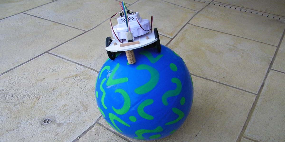
Balancing a Robot on a Ball
By John Blankenship View In Digital Edition
Assume you have a mobile robot sitting on a large ball. Imagine programming the robot so that if the ball is moved, the robot will climb to the top of the ball and level itself. If building such a robot excites you, this article will demonstrate some key points to help get you started.
When it comes to balancing robots, a lot has been written on two-wheel Segway-like robots. They can be both interesting and challenging for sure, but if you have read some of my previous articles, you know I often like to find a different approach to standard topics.
My inspiration for a different kind of balancing project came from the Star Wars BB-8 shown in Figure 1. When I first saw pictures of the robot, I assumed the large ball was being moved by wheels on the head. If you watch the robot in action, though, you see that the head can tilt far to one side when the ball is sitting still (as if the robot is peeking around a corner, for example). Obviously, this means the head is not the controlling mechanism.

FIGURE 1.
A search of the Internet can reveal details of the inner workings of the BB-8. The wheeled propulsion mechanism sits inside the body at the bottom of the ball. This assembly can move the ball in any direction, but it can also rotate and tilt a curved arm that rides near the inner surface of the upper half of the ball. The head attaches to this arm magnetically allowing the head to move totally independent of the body’s orientation.
Building a BB-8 using an internal mechanism should be within the talents of many hobbyists because the low center of gravity of the propulsion unit should make programming relatively simple. For that reason, I was more intrigued with the possibility of placing a typical mobile robot on top of a ball and letting the movements of the mobile robot control the movement of the ball.
The first step in achieving such an action is to prove that a mobile robot can constantly level itself on top of a moving ball. Figure 2 shows the robot in action.
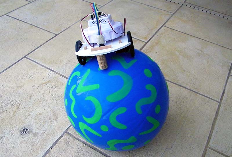
FIGURE 2.
Constructing the Hardware
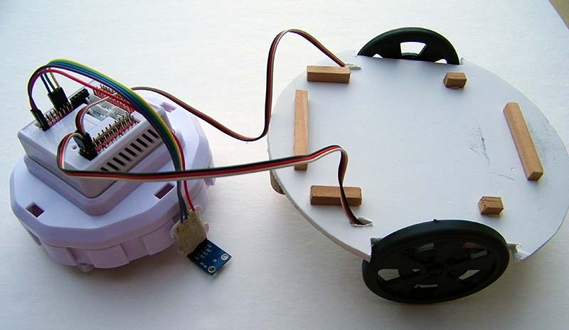
The robot shown in Figure 2 is one I had used for a previous project. It’s powered with 360-degree servo motors (Figure 3) and controlled with an EZ-Robot controller (Figure 4). The controller had numerous ports, an integrated battery, and Internet communications, so it made it easy to implement a simple feasibility test.
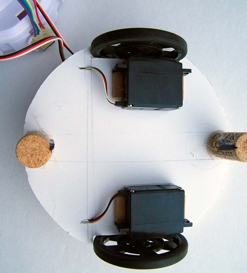
FIGURE 3.
FIGURE 4.
Sensing Tilt
In order to balance atop the ball, the robot must be able to determine its tilt orientation. I used an ADXL 335 accelerometer with analog outputs as shown in Figure 5 to obtain the robot’s orientation. The ADXL 335 provides an output voltage for each axis that is proportional to the actual tilt. If you look carefully at Figure 4, you can see this sensor attached to the front of the EZ-Robot controller.
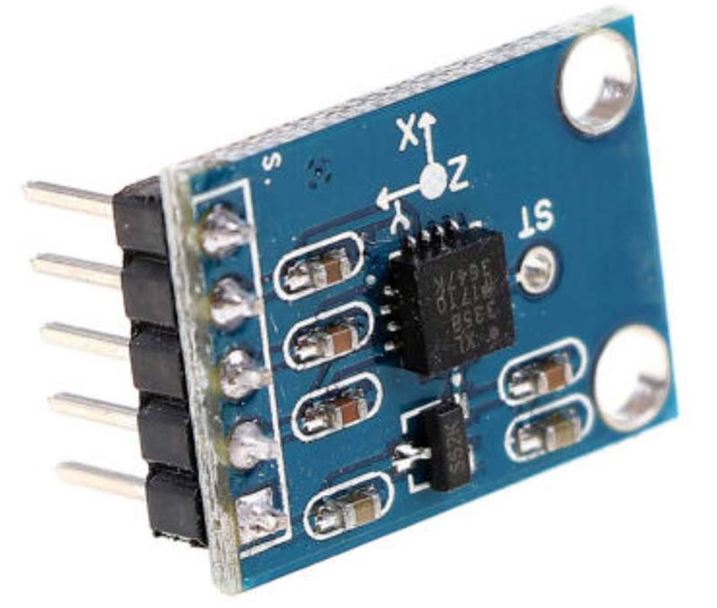
FIGURE 5.
The sliding caster assemblies originally used to maintain balance on the mobile robot I used had too much friction against the ball’s surface, so I replaced them with wine corks (one on the front and another on the back as shown in Figure 6). Each cork is tipped with one prong from a plastic fork (hot glue is wonderful). The tiny points at the end of the prongs move easily over the surface of the ball.
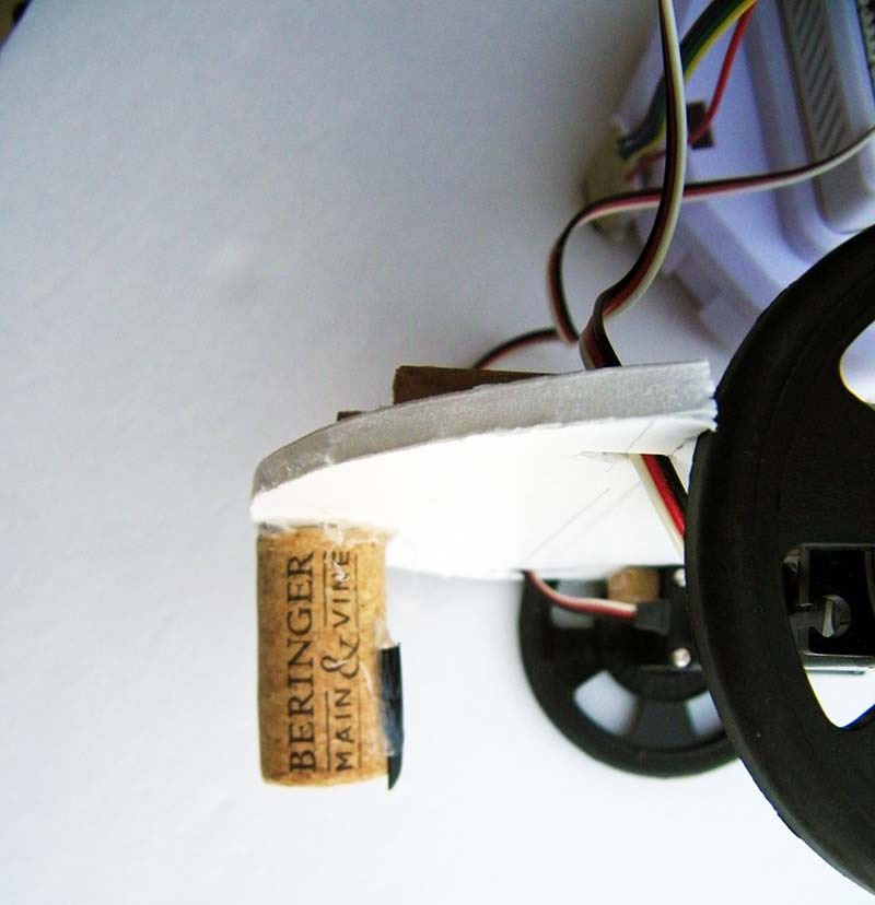
FIGURE 6.
Programming the Robot
After the hardware construction was completed, I was anxious to find out how hard it would be to program the robot to maintain its position on the top of the ball. EZ-Robot has the option of programming their controller with a primitive version of Blockly. This made testing extremely easy, but I will probably switch to a Parallax Propeller (and Parallax’s more advanced Blockly language) if I decide to explore a more sophisticated version of this project.
I will confess that I wasn’t sure how difficult it would be to create a self-leveling program. Figure 7, however, shows a very simple program that works far better than I expected.
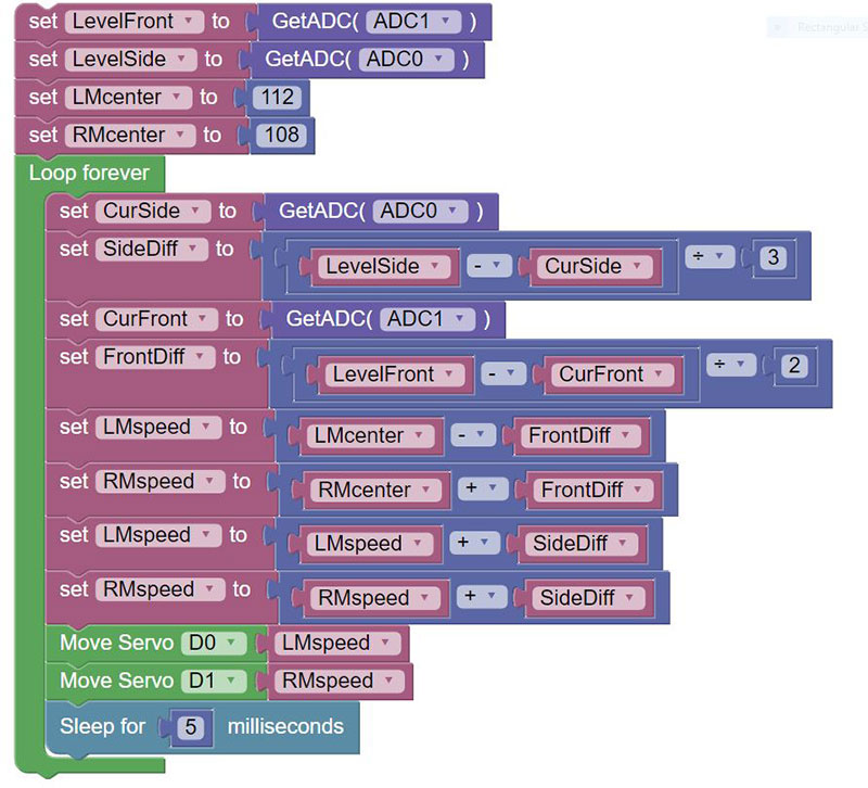
FIGURE 7.
The robot should be placed in a level position at the top of the ball before starting the program. This is required because the program starts by reading the tilt values from the accelerometer and stores them in the variables LevelFront and LevelSide to be used as level reference values.
Next, two variables are initialized to the center (stopped) values for the wheel servos. Subsequent tilt readings from the accelerometer will be used to control the wheel speeds by deviating the servo pulses from these specified center values.
The endless loop in Figure 7 obtains the current forward and side tilt values from the accelerometer and stores them in CurFront and CurSide. In each case, the new value is compared to the stored reference values for a level robot, and the difference is stored in the variables FrontDiff and SideDiff.
Notice that each difference value is divided by a scale factor (obtained from experimentation) to create a suitable value for the next operation.
The FrontDiff is added to the center value for one wheel’s servo and subtracted from the other. The reason the value is added to one and subtracted from the other is because the wheel servos are mirror images of each other (meaning to get both motors to move the robot in the same direction, the pulse to one must be increased while decreasing the pulse to the other).
The net result of this action is that both motors will either move forward (or backward) at a speed based on the value of FrontDiff. This just means that the further the robot is tilted forward (or backward) on the ball, the faster it will move, trying to get back on top.
The value of SideDiff is used in a similar way except that it’s added to both wheels (or effectively subtracted if the difference value is negative). This means that one wheel will move forward and the other will move backward, causing the robot to rotate around its center until the side tilt is eliminated, effectively ensuring that the robot is facing the top of the ball. At that time, the robot’s forward tilt will cause it to climb to the top of the ball.
It’s important to emphasize that this algorithm changes the wheel speed based on the difference in the robot’s current tilt compared to the desired level position — the more tilt, the faster the robot moves. This means the robot’s speed will be proportional to the error between the current tilt and the desired level position.
Since we’re only using the proportional aspect instead of full PID (proportional, integral, differential) control, the program is not good enough to make the robot balance on a fast-moving ball. I found it very pleasing, though, to see the robot easily level itself at the top of the ball as I manually rolled it around at moderate speeds.
Final Thoughts
The program in Figure 7 demonstrates that a mobile robot can level itself on a slowly moving ball. The program has its limitations, but it certainly demonstrates the feasibility of a ball-balancing robot. The next logical step is to implement a more rigorous algorithm using a more capable language.
Once the robot can stay balanced on a freely moving ball, it should take minimal effort to make the robot move the ball around under remote control. Interested readers are encouraged to explore this challenge. SV
Article Comments